240 L4-2320cc 2.3L SOHC VIN 83 B230FD (1993)

Valve: Adjustments
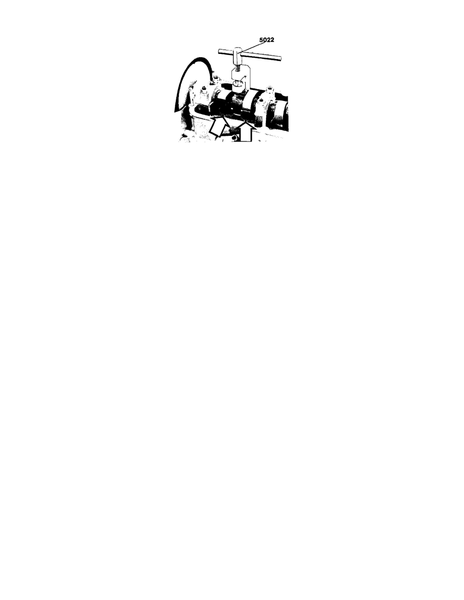
Fig. 7 Valve Adjustment
1.
Remove valve cover.
2.
Rotate engine until both valves for #1 cylinder are on the heel of cam lobes.
3.
Insert feeler gauge between cam lobe and valve shim to check clearance. Clearance on should be .012-.016 inch, if clearance is incorrect, line up
valve depressors so notches are at right angles to engine center line arrows in Fig. 7.
4.
Attach adjustment tool No. 5022 or equivalent. Screw down tool spindle until depressor groove is just above edge of head and accessible with
pliers, Fig. 7.
5.
Use special pliers tool No. 5026 or equivalent and remove valve shim.
6.
Use a micrometer to measure shim thickness. Calculate shim thickness necessary to obtain correct clearance.
7.
Coat new shim with oil and install it in valve depressor with marking facing downward.
8.
Repeat adjustment procedure for cylinders 3, 4 and 2.
