
240 L4-2320cc 2.3L SOHC VIN 83 B230FD (1993)
Engine Control Module: Description and Operation
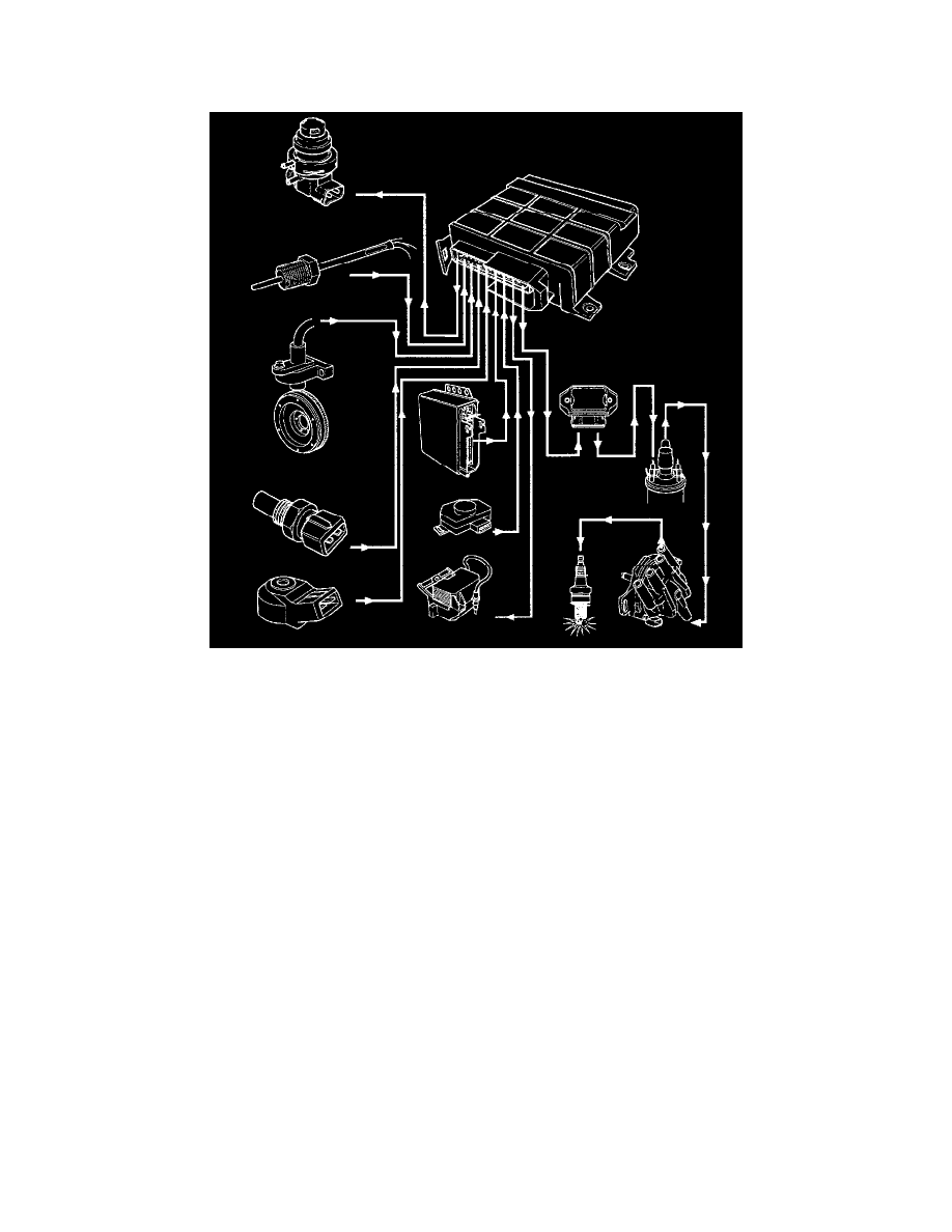
The DI System Can Be Divided Into Five Sub-systems.
-The Sensor System sends information to the control system required to achieve optimum control of the ignition.
-The Control System ensures that optimum ignition timing and ignition voltage are obtained for each ignition.
-The High Tension System produces and distributes high tension voltage.
-The On-board Diagnostic (OBD) system has three test functions to facilitate fault tracing. The OBD system works commonly for the fuel system,
the TO control system and the DI system.
-The EGR System reduces the emission of nitrogen oxides.
Control Module Monitoring Functions
The control module has a reversible limp-home mode. This means that if a signal returns to a reasonable value after it has been faulty, the control will
utilize this value again rather than remaining in limp-home mode.
- If there is no signal from the KS the ignition is retarded approx. 10°.
- If there is no load signal from MFI LH 2.4 or LH 3.1, ignition timing is calculated for full load except when the TP switch indicates that the engine is
idling.
-If there is no engine temperature signal, ignition timing is based on the engine being warm.
- If there is no TP signal, the control module takes account of load when the engine is idling.
Ignition Timing Control