
240 L4-2320cc 2.3L SOHC VIN 83 B230FD (1993)
Clutch Switch: Description and Operation
Design and function
The system is in two main parts:
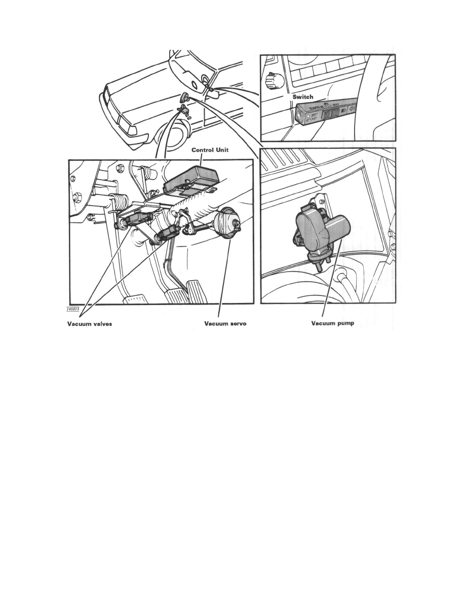
The switch is integrated with the direction indicator switch. It controls the system by sending signals to the control unit.
The electronic control unit is mounted above the pedals. It receives signals from the switch in the direction indicator stalk, from the speedometer and
from the vacuum valves. It controls the vacuum pump by means of a signal proportional to the speed.
Vacuum pump, with built-in vacuum valve, mounted in the engine compartment on the bulkhead. The vacuum pump controls the vacuum servo
pressure which actuates the throttle control through a system of linkages.
Vacuum valves, which are actuated by the brake and clutch pedals and contains electrical switches. When the brake or clutch is used, the vacuum
valves switch off the control unit electrically and discharge the vacuum system.