
240 L4-2320cc 2.3L SOHC VIN 83 B230FD (1993)
FE2
Connecting The Test Box
-Connect the test box to DI and check the GND points in accordance with P3-P4.
FE3
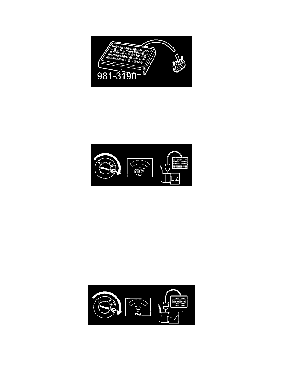
Checking The RPM Sensor Signal
-Connect the control module to the test box.
-Re-install system fuse.
Connect a voltmeter between #10 and #23.
-Operate the starter motor.
The voltmeter reading should be at least 5OOmV AC.
If the reading is OK
-Check the engine speed signal FE4.
If the reading is incorrect
-Check the wiring between the RPM sensor and control module for loose contacts.
FE4
Checking The Engine Speed Signal From ICM To MFI Module
With the test box connected to the DI module connect a voltmeter between DI#1 7 and #20 (GND).
The voltmeter should read 7-8 V.