
240 L4-2320cc 2.3L SOHC VIN 83 B230FD (1993)
5.
Remove connector protective sleeve.
IMPORTANT:^ Never check connections from the front. Connectors can get damaged and worsen the problem.
^ Check connections through the holes in the connector.
^ Connection pin numbers are printed on the connector side.
Checking Gear Selector Signal
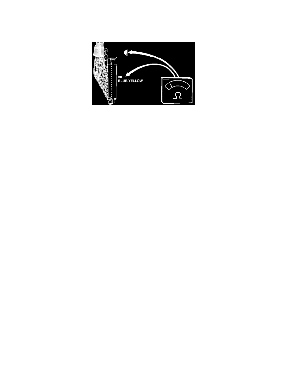
6.
Put gear selector in N (neutral) position.
7.
Connect an ohmmeter between ECU connector pins 30 and ground.
Reading: 0 ohm
8.
Put gear selector in D (drive) position.
9.
Check resistance.
Reading: infinite (the reading should be 0 ohm on vehicles with manual transmission)
10.
If switch fails the test, check wiring and connectors. If no fault found in wiring, replace gear selector switch.
11.
After testing, disconnect all test equipment, reconnect all connectors (including the ECU connector) and remount all panels.