
240 L6-2383cc 2.4L DSL SOHC D24 FI (1982)
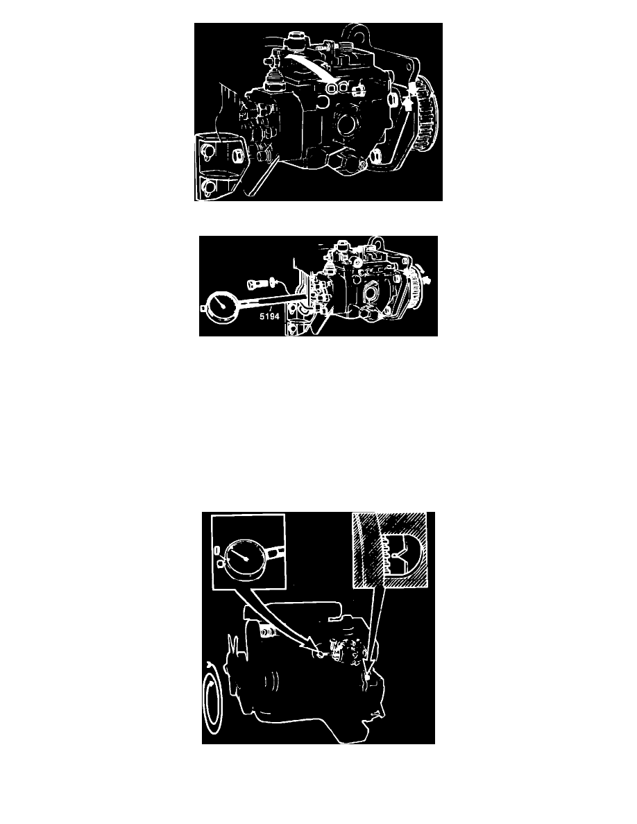
Fig. 10 Alignment of injection pump marks
Fig. 12 Installing dial indicator on injection pump
4.
Remove plug at end of injection pump distributor and install holder 5194 and a dial indicator with a range of 0-3 mm (0-0.118 inch), Fig. 12. Set
indicator at 2 mm (0.079 inch) and turn injection pump sprocket until marks on sprocket and bracket coincide, Fig. 10.
5.
Turn injection pump sprocket slightly counterclockwise until dial indicator shows minimum reading. Set indicator to zero. Turn sprocket slightly
clockwise until marks on sprocket and bracket coincide. Lock sprocket in this position with stop 5193 or equivalent. Insert stop through hole in
sprocket and bracket.
6.
Install rear sprocket on camshaft. Tighten center bolt so sprocket can rotate on camshaft and install drive belt.
7.
Use injection pump bracket to tighten pump drive belt. Set belt tension using gauge 5197 or equivalent. Place gauge on belt and set to 12.5 and
tighten belt until mark on plunger is flush with tool sleeve. Tighten pump bolts and recheck tension.
8.
Use wrench 5199 or equivalent to hold rear camshaft sprocket and place wrench 52 01 on center bolt. Place torque wrench on wrench 5201 at right
angle to get accurate readings. Turn sprocket until indicator reads 0.70 mm (0.028 inch) on D24 engine, or 0.80 mm (0.031 inch) on D24T engine.
Hold sprocket in this position and torque center bolt to 73 ft. lbs. (100 Nm). Make sure camshaft and sprocket do not change position.
Fig. 13 Checking injection pump setting
9.
Rotate crankshaft two full turns until No. 1 cylinder is at TDC and injection position (compression stroke), Fig. 13. If engine is turned too far, turn