
240 L6-2383cc 2.4L DSL SOHC D24 FI (1982)
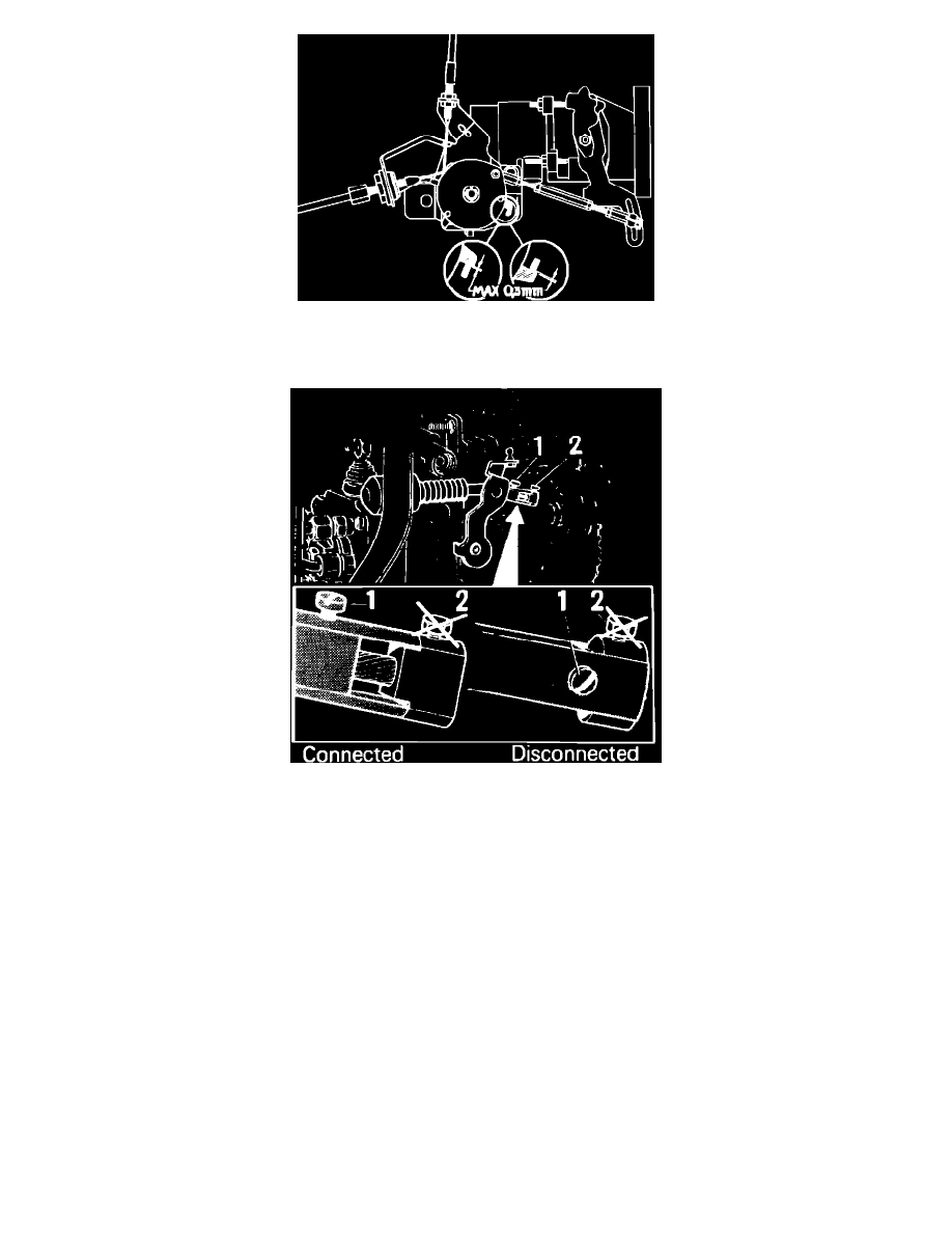
Fig. 11 Setting accelerator controls
15.
Set accelerator controls, Fig. 11, as follows:
Fig. 9 Connecting and disconnecting cold start device
a. Disconnect cold start device, Fig. 9, and link rod at injection pump lever.
b. Adjust accelerator cable by turning cable sheath until cable is under tension but does not alter pulley position. Pulley should be at idle stop.
c. Depress accelerator pedal fully and check maximum accelerator position. Pulley should contact full throttle stop.
d. On automatic transmission models, kickdown cable should move about 2 inches between end positions when accelerator is floored. Cable
should be under tension in idle position, and distance between kickdown cable clip and cable sheath should be 0.01-0.04 inch (0.25-1.00
mm).
e. Connect link rod to injection pump lever. Turn pulley to full throttle position and adjust link rod length so that pump lever contacts maximum
speed adjusting screw.
f.
Turn pulley to idle stop and move link rod ball joint in slot in injection pump lever until lever contacts idle adjusting screw.
g. Readjust link rod by repeating steps e and f until control is correctly adjusted. A maximum clearance of 0.012 inch (0.3 mm) is permissible at
pulley stops.
h. Reconnect cold start device.