
760 L4-2320cc 2.3L SOHC Turbo B23FT (1984)
Positive Crankcase Ventilation: Description and Operation
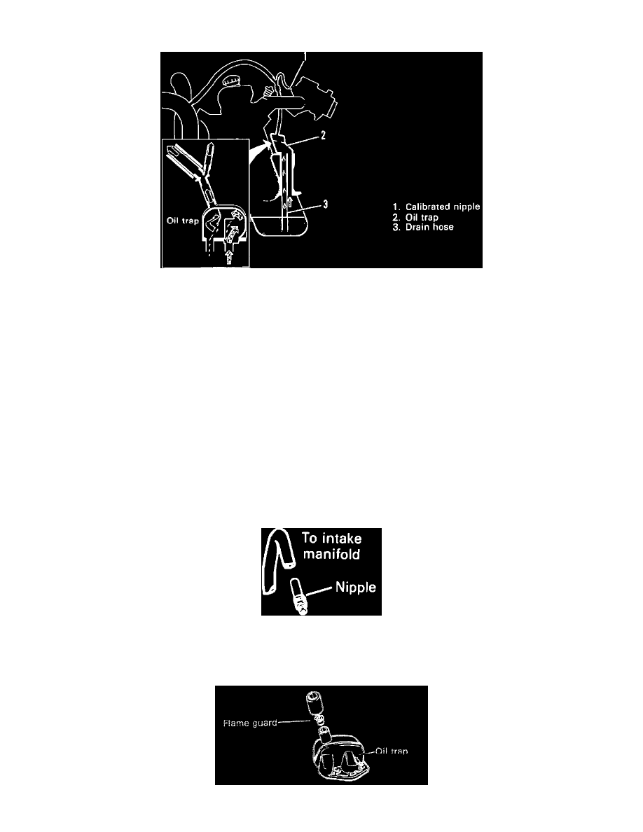
Fig. 13 POSITIVE CRANKCASE VENTILATION SYSTEM
The crankcase emission controls prevent crankcase gases from being released into the atmosphere. Instead, the gases are routed to the intake manifold.
Crankcase gases are removed from the crankcase by positive crankcase ventilation (PCV). Intake manifold vacuum draws the crankcase gases into the
intake air, where they get ignited in the combustion process. Fig. 13.
Between the crankcase and the intake manifold there is a hose which is connected to a nipple on the intake manifold. Between the valve cover and the
air cleaner there is a hose connected for fresh air supply.
The partial vacuum that exists in the intake manifold during engine operation, creates a vacuum in the crankcase through the hose. Fresh air is supplied
to the valve cover by the air cleaner and hose. A plate in the valve cover ensures that the fresh air circulates sufficiently in order to mix with the
crankcase gases.
As fresh air passes through the air cleaner, impurities are prevented from entering the engine. During high or medium amounts of vacuum in the
crankcase, which occurs during idling and when under light loads, the system operates as described above. When vacuum in the crankcase is less then
that in the air cleaner, which occurs at full load and/or with large air-flow quantities, no fresh air is supplied. Instead, the flow in the connection
between the valve cover and the air cleaner reverses and the crankcase gases pass both ways. In this way, the PCV system can deal with relatively large
quantities of crankcase gases without any entering the atmosphere.
COMPONENTS:
----------------
Fig. 9 P.C.V. NIPPLE
NIPPLE
Regulates the crankcase gas flow and limits the maximum crankcase vacuum. Fig. 9.