
760 L6-2383cc 2.4L DSL Turbo D24T (1983)
Valve Clearance: Adjustments
1.
Remove valve cover and turn engine to firing position for No. 1 cylinder. Flywheel timing mark should be at 0 and No. 1 cylinder cam lobes
should point up at equal angles.
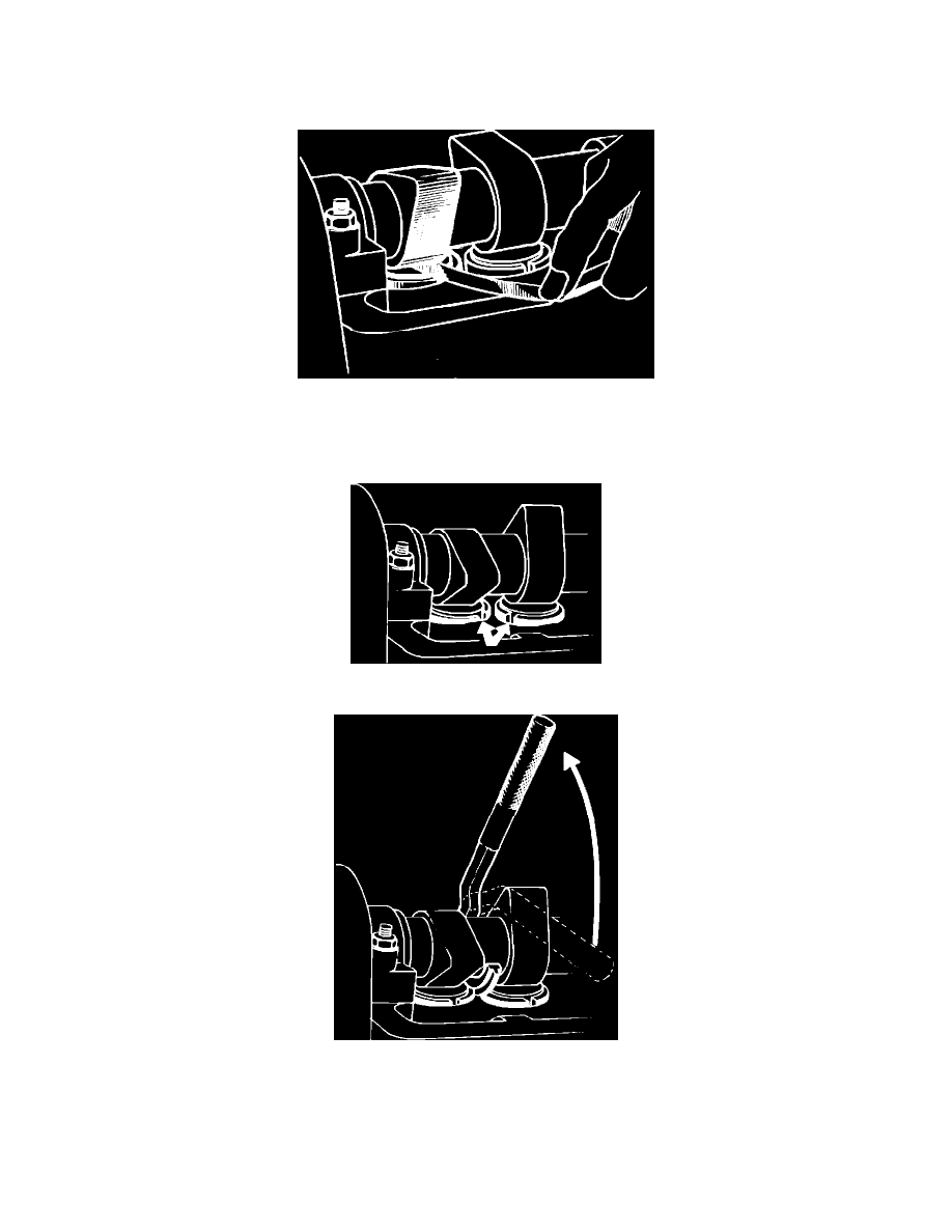
Fig. 3 Checking valve clearance
2.
Check valve clearance by placing feeler gauge between cam and tappet, Fig. 3. Refer to ``Valve Specifications.''
3.
If clearances are not within specifications, turn engine approximately 1/4 turn to allow adequate clearance for depressing valves.
Fig. 4 Aligning valve tappets
Fig. 5 Depressing valve tappets
4.
Turn valve tappets until notches point slightly inward, Fig. 4. Use tool 5196 or equivalent to depress valve tappets, Fig. 5. Tappet grooves must
point so that disc can be gripped with pliers 5195 or equivalent.
5.
Remove disc and use micrometer to measure disc thickness. Determine disc thickness necessary to obtain correct clearance. Discs are available in
thicknesses of 0.1299 inch (3.30 mm) to 0.1673 inch (4.25 mm) in increments of 0.002 inch (0.05 mm). Use only new discs.
6.
Oil disc and position with numbers facing down.