
780 V6-2849cc 2.8L SOHC B280F (1987)
S4
Door switch
S5
+ 12 V (30 feed)
S6
-
S7
-
S8
Vibration sensor, RH B-post
S9
Vibration sensor, LH B-post
S10
-
S11
+ 12 V (15 feed)
S12
Start inhibitor relay
S13
Ground
S14
Alarm relay
S15
Vibration sensor, RH B-post
L1
Windshield switch unit,
ground (SB)
L2
Windshield switch unit (BL)
L3
Windshield switch unit (GR)
L4
Windshield switch unit (R)
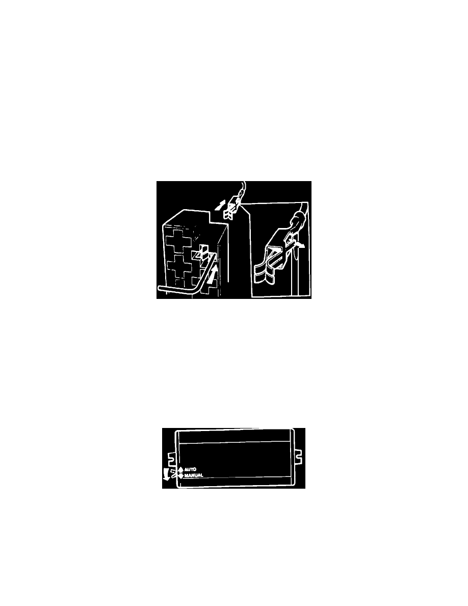
Most of the following fault tracing procedures involve disconnecting a lead from the alarm unit.
The procedure is as follows:
Disconnect connector from unit.
Use a needle or similar implement to press down hook on top of sleeve to be removed, and press out sleeve.
Reinstall connector and carry out faulttracing procedure.
Remove connector again and reinstall sleeve. (Pry up hook slightly before inserting sleeve.)
Reinstall connector.
Alarm unit switch should be set to MANUAL during all fault-tracing procedures.
Note:
As used in the following description, the term "energized" denotes that the alarm is activated and will sound if the car is interfered with.
"De-energized" means that the alarm has been deactivated without implying that the alarm has operated.
Fault-Tracing Procedure 1, 2, 3, & 4