
780 V6-2849cc 2.8L SOHC B280F (1987)
Engine Control Module: Connector Views
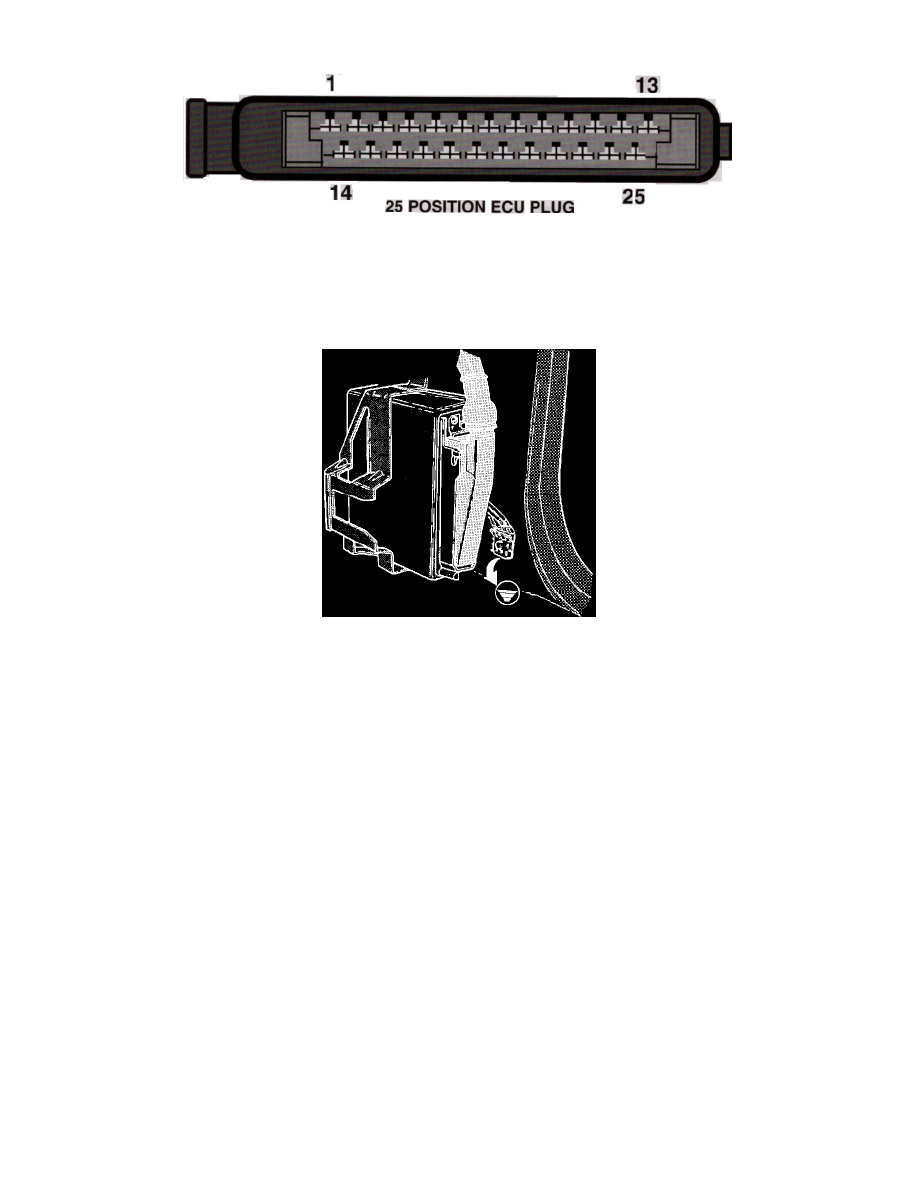
25 Position ECU Plug
PIN LAYOUT
SYSTEM
LH-Jetronic
Checking ECU Ground Connections
LOCATION
Passenger side kick panel
TERMINAL ID
1 - Coil (-) Trigger signal input (Gray)
2 - Coolant Temperature Sensor (Blu)
3 - Idle Switch (Org)
4 - Start input (Blu/Yel)
5 - Shield Ground 2 wires (Gry) (Grn)
6 - Air Mass Meter Ground (Grn/Yel)
7 - Air Mass Meter Load (Wht/Red)
8 - Air Mass Meter Burn-off (Wht)
9 - Main Relay Supply (Brn)
10 - ISC Valve Control (Wht)
11 - Ground (Blk)
12 - Full Load Throttle Switch (Wht/Blk)
13 - Injector Driver Output (Grn/Wht)
14 - Air Mass Meter CO Adjustment (Yel)
15 - Idle defeat (2.0 Ver.) Trans Sw. (Blu/Wht)
16 - Air Conditioning Micro Switch (Red)
17 - Fuel Pump Relay Control (Blu/Grn)
18 - Ignition Switch Power (Blu/Red)
19 - Low Octane Adjust
- No wire in 2.0 version.
20 - Oxygen Sensor Input (Grn)
21 - Main Relay Control (Yel/Red)
22 - Integrator Output (Pnk)
23 - ISC Valve Control (Grn/Red)