
780 V6-2849cc 2.8L SOHC B280F (1987)
5.
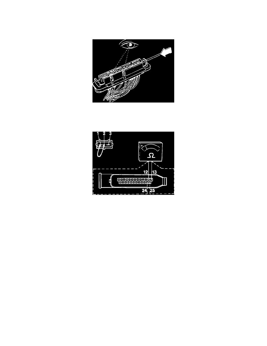
Remove connector protective sleeve.
IMPORTANT:^ Never check connections from the front. Connectors can get damaged and worsen the problem.
^ Check connections through the holes in the connector.
^ Connection pin numbers are printed on the connector side.
Checking Terminal Pins
6.
Check that terminal contacts have been pushed down evenly in connector.
7.
If any connectors have been pushed down to far, poor connection may result.
Checking Knock Sensors
8.
Check wiring by removing the connector at the fuel distributor pipe. Install a bridge wire between terminal 1 and 2.
9.
Connect an ohmmeter between pin 12 (black) and 13 (gray) and then between pin 24 (brown) and 25 (green) at ECU connector.
Reading: 0 ohm in both cases
10.
If resistance is to high, remove bridge wire and check each wire separately for resistance.
a. Replace damaged wire(s).
b. If wires are not damaged, replace knock sensor or if possible, check knock sensor as described below under DYNAMIC TESTING
PROCEDURE. Replace as necessary.
11.
After testing, disconnect all test equipment, reconnect all connectors (including the ECU connector) and remount all panels.
DYNAMIC TESTING PROCEDURE:
The sensors can only be tested dynamically with the use of an oscilloscope.
1.
Turn ignition ON.
2.
Probe the two terminals at each knock sensor.