
780 V6-2849cc 2.8L SOHC B280F (1987)
Knock Sensor: Description and Operation
Knock Sensor
Used by the ignition ECU:
PURPOSE AND LOCATION
The knock signal is generated by one or both of the two knock sensors (one for each cylinder bank). The sensors are located underneath the intake
manifold, in the engine block in center of each cylinder bank. When engine knock is detected, the knock sensor develops a voltage which the ignition
ECU registers. The ECU then takes appropriate action by retarding the ignition timing to eliminate knock.
CONSTRUCTION
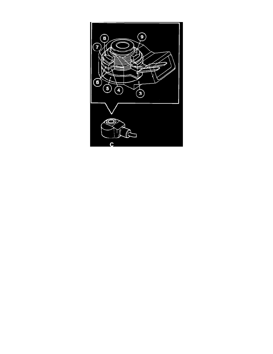
The knock sensor (C) consists of a housing (3) a piezoelectric crystal (4) mounted on a threaded sleeve (5) between two connector strips (6). One side of
the assembly is fitted with a damping weight (7) and spring washer (8) secured by a nut (9).
OPERATION
Mounted on the engine block, the sensors are subjected to the vibrations generated by knock. The vibrations cause a small distortion on the surface of
the piezoelectric crystal, which consequently generates a small voltage. This voltage is read by the ignition ECU.
SIGNAL
The signal from the sensors is a continuous, but variable voltage. The frequency of the voltage is dependent on the amount of engine knock. The signal is
fed into the ignition ECU which computes it as a reference value.