
850 L5-2.3L Turbo VIN 57 B5234FT (1994)
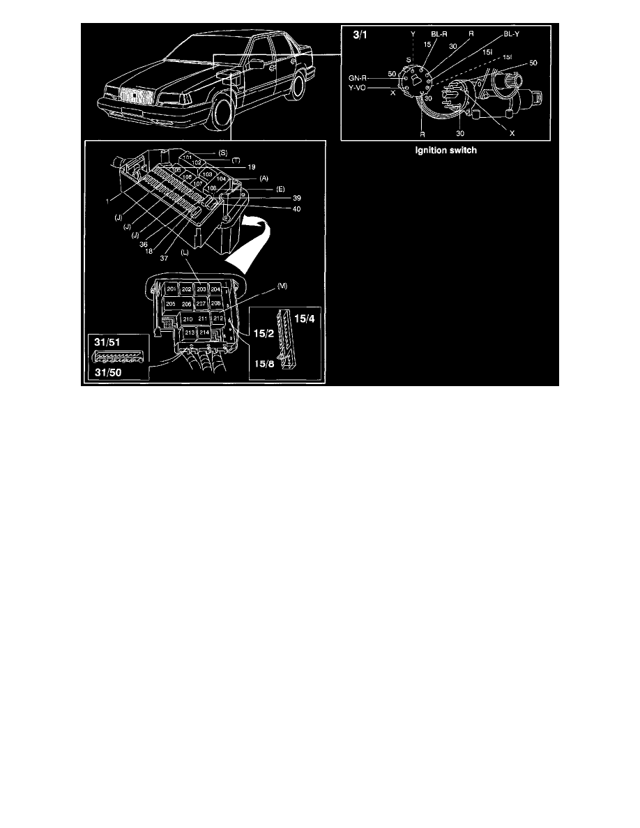
Ignition Switch And Central Electrical Unit, Fuses And Relays
Ignition Switch And Central Electrical Unit
Connection Rails In Central Electrical Unit
15/2 30 rail
15/4 15I rail
15/8 X rail
31/50 Ground connection rail (power ground)
31/51 Ground connection rail (signal ground)
Relays In Central Electrical Unit
101-102 Control module, cruise control (4/3)
103 Fuel pump relay (2/23)
104,108 Main headlight relay with bulb malfunction indicator (2/1)
105 Overload relay +X supply (2/30)
106 Overload relay +15 supply (2/31)
107 Overload relay +X supply (2/60)
201 Control module, oil level sensor (4/18)
202 Relay, deadlock setting (2/47)
203 Relay, windshield intermittent wiper (2/4)
204 Relay, tailgate intermittent wiper (2/16)
205-206 Relay, central lock and delayed inside lighting (2/7)
207 Speed warning (2/51) or exhaust temp. sensor relay (2/15)
208 Relay, heated rear window and door mirrors (2/44)
210-211 Relay, anti-theft alarm (2/28)
NOTE: If the car is not equipped with a theft alarm, position 210 is bridged and 211 is unconnected.
212 Relay, seat belt reminder/key warning (2/5)
213 Relay, P-shift lock (2/45)
214 Relay, heated rear seat (2/43)