
850 L5-2.3L Turbo VIN 57 B5234FT (1994)
31/11
Ground point, trunk, left side
31/12
Ground point, trunk, right side
31/15
Ground point, A-post passenger's side
31/32
Ground point on engine (power ground)
31/33
Ground point on engine (signal ground)
31/44
Ground point, engine compartment (ground connection battery - body)
31/47
Ground point, left cross member
31/48
Ground point, right cross member
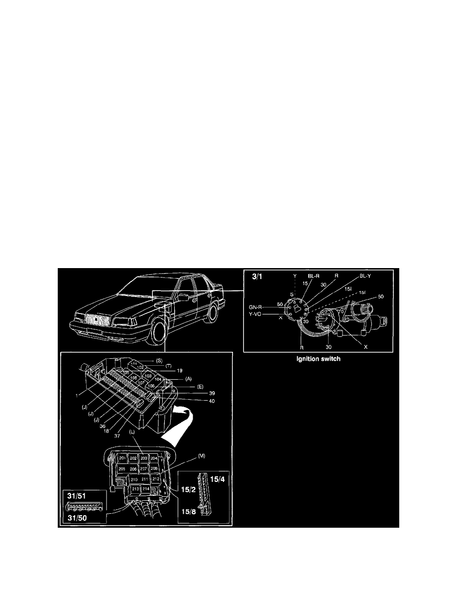
31/50
Ground point, central electrical unit (power ground)
31/51
Ground point, central electrical unit (signal ground)
31/52
Ground point, DI power stage and ignition coil
31/55
Ground point, engine cooling fan
31/65
Ground point, steering column
Wire Color Code Identification
SB
= Black
GR
= Grey
W
= White
R
= Red
BN
= Brown
Y
= Yellow
P
= Pink
BL
= Blue
GN
= Green
OR
= Orange
VO
= Violet
Y-GR = Yellow-Grey
Connector 3/1 (Ignition Switch)
Ignition Switch And Central Electrical Unit, Fuses And Relays
Ignition Switch