
850 T-5R L5-2.3L Turbo VIN 58 B5234T5 (1995)
Hydraulic Control Assembly - Antilock Brakes: Service and Repair
NOTE:
Hydraulic unit must be replaced as a complete unit. Hydraulic unit must not be opened under any circumstances. Reassembling it requires special
equipment and facilities.
The hydraulic unit, reducing valve and control module are on the same bracket in the engine compartment. It hydraulic unit has to be changed, the
whole bracket must be removed first before the hydraulic unit can be removed from its mounting.
Preparations [NE1]
-
Ignition off.
-
Remove battery negative lead.
Removing bracket [NE2]
-
Drain system of brake fluid.
-
Clean brake hose and pipe connections on hydraulic unit and master cylinder.
-
Put rags under hydraulic unit to protect painted surfaces in the event of a brake fluid spillage.
-
Remove complete air filter casing.
In turbo models:
-
Remove inlet pipe between filter casing and turbocharger unit.
[NE3]
-
Remove the two brake pipes to the reducing valve from the master cylinder.
-
Remove the three brake pipes (cars with TRACS have a fourth brake pipe from the reducing valve) from the side of the hydraulic unit. Seal off the
brake pipes and connectors on hydraulic unit immediately to prevent dirt getting into the system.
[NE4]
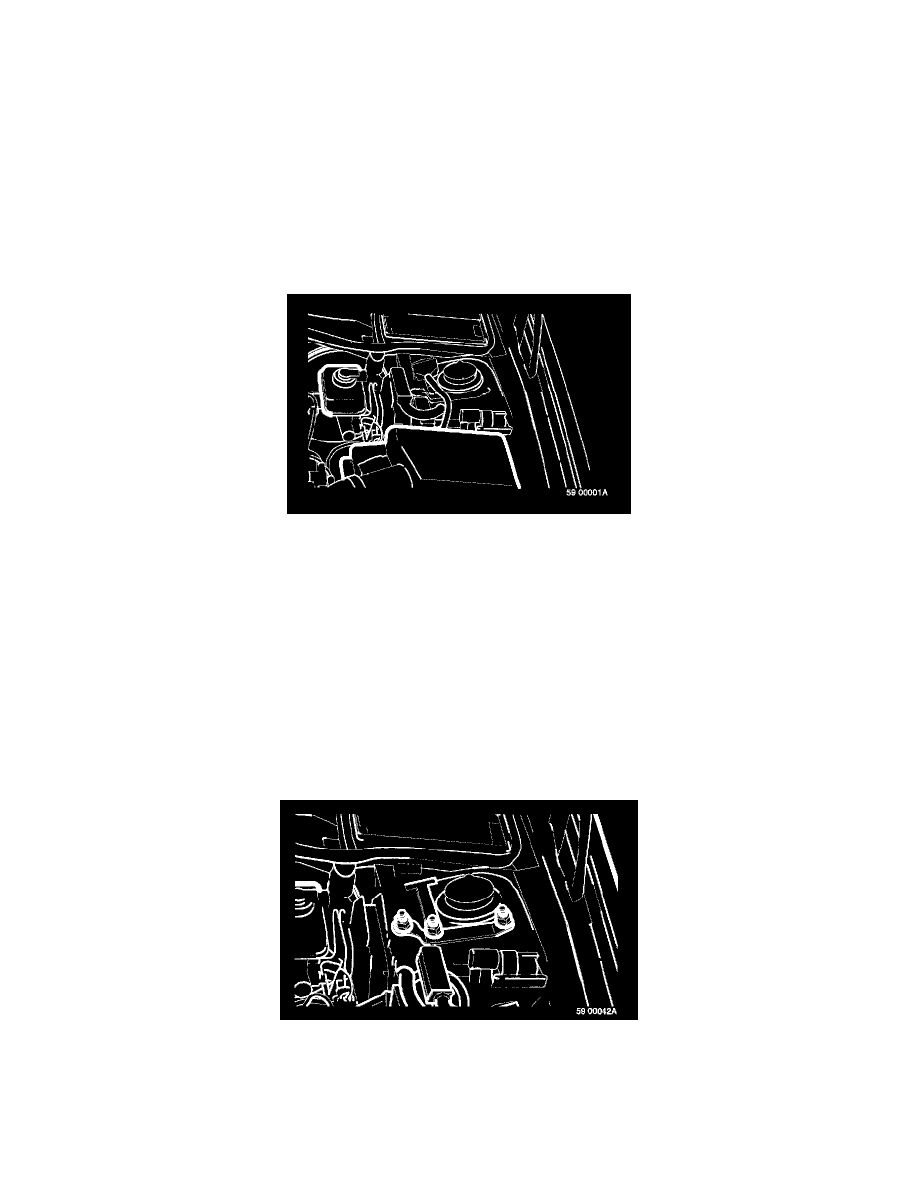
-
Remove the 15-pin connector between hydraulic unit and engine leads (on top of shock absorber turret).
-
Remove the two bolts holding the connector to the mounting.
-
Twist the leads to this connector together with the lead to the control module 55-pin connector to avoid confusion.
[NE5]
-
Remove combination relay from mounting.