
850 T-5R L5-2.3L Turbo VIN 58 B5234T5 (1995)
Data Link Connector: Description and Operation
Diagnostic Connectors
PURPOSE
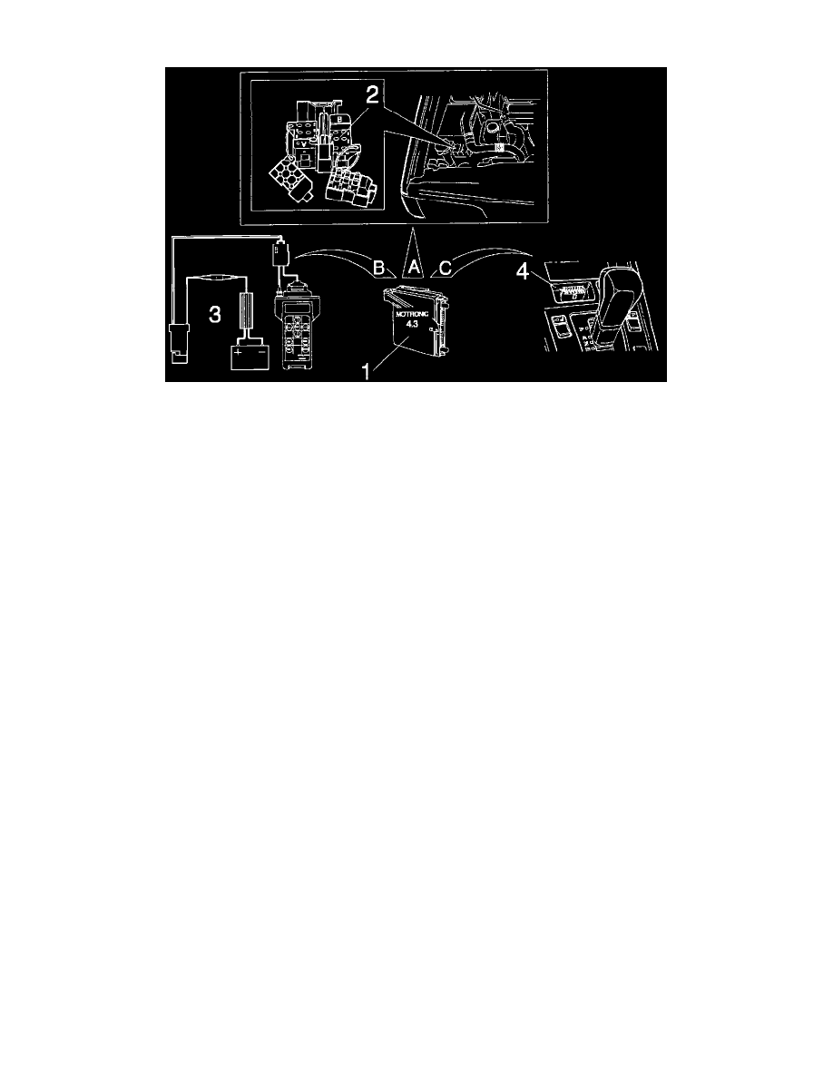
The data link connector (DLC) is used for communication with the diagnostic functions in the ECU. Communication can be established three
ways:
- using the OBD II connector (4) and a standard scan tool
- using the Volvo scan tool (3)
- using the diagnostic socket (2)
A brief description of diagnostic socket operation follows. Additional information is located under System Diagnosis.
OPERATION
The diagnostic socket consists of a button, an LED and a selector cable. To fault trace the system, the selector cable is placed in output #2. By
pressing the button once, twice or three times (depending on control function required), the ECU is accessed.
Control function #1:
This control function accesses the fuel injection ECU memory and extracts any recorded faults.
Faults stored in the ECU are read via "fault codes" consisting of flashes at the LED.
Control function #2:
This function tests selected input components in the fuel injection system.
Control function #3:
This function tests selected output components. Components are automatically tested and activated to check for correct operation.