
850 T-5R L5-2.3L Turbo VIN 58 B5234T5 (1995)
Instrument should indicate battery voltage.
If reading is correct:
^
Check lead between front terminal on fuseholder for fuse 15 and OBD DLC II unit terminal 16 for open-circuit as per [LA2].
^
Proceed to step A6 "Checking Volvo Diagnostic communications interface".
If reading Is Incorrect:
^
Check lead between fuse 15 and battery positive terminal for open-circuit as per [LA2].
^
Proceed to A6 "Checking Volvo Diagnostic communications interface".
A6
CHECKING VOLVO DIAGNOSTIC COMMUNICATIONS INTERFACE
-
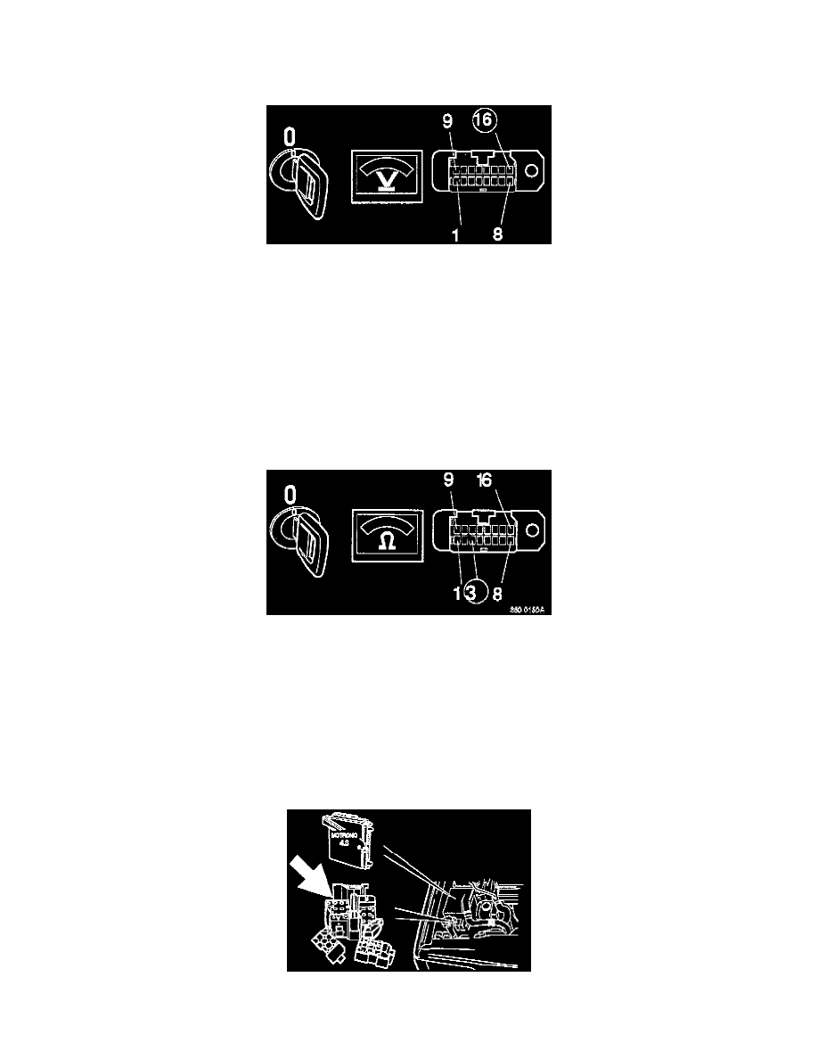
Switch off ignition.
Connect ohmmeter between OBD II DLC terminal 3 and cigarette lighter ground.
Instrument should indicate 10-20 kOhm.
If reading Is correct:
^
Proceed to step A7 "Checking OBD II communications interface".
If Instrument Indicates approx. 0 ohm:
^
Check leads between OBD II DLC terminal 3 and Motronic 4.3 SFI/DI engine control module (ECM) # B5, and between terminal 3 and DLC
(A) terminal 2 for short-circuit to ground as per [LA3].