
850 T-5R L5-2.3L Turbo VIN 58 B5234T5 (1995)
^
Proceed to step A7 "Checking OBD II communication Interface".
If instrument indicates infinity:
^
Check lead between OBD II DLC terminal 3 and ECM # B5 for open-circuit as per [LA2].
^
Proceed to step A7 "Checking OBD II communications interface".
A7
CHECKING OBD II COMMUNICATIONS INTERFACE
-
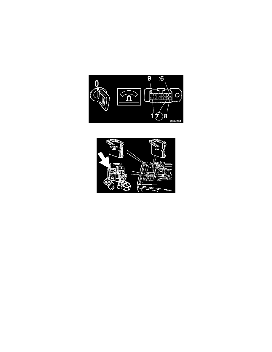
Switch off ignition.
-
Disconnect transmission control module (TCM) if installed.
Connect ohmmeter between OBD II DLC terminal 7 and cigarette lighter ground.
Instrument should indicate 90-110 kOhm.
If reading Is correct:
^
OBD II DLC is OK.
If Instrument indicates approx. 0 ohm:
^
Check leads between OBD II DLC terminal 7 and ECM # 836, and between DLC (A) terminal 6 and TCM # 822, for short-circuit to ground as
per [LA3].
If instrument indicates infinity:
^
Check lead between OBD II DLC terminal 7 and ECM # 836 for open-circuit as per [LA2].
WARRANTY STATEMENT: Claims may be submitted under the New Car Limited Warranty when a manufacturing defect is present using claim type:
01
Operation No. Description Time allowance
280723
Checking OBD II data link connector..........................................................................................................................................................0.4 hr