
850 T-5R L5-2.3L Turbo VIN 58 B5234T5 (1995)
Control Module HVAC: Description and Operation
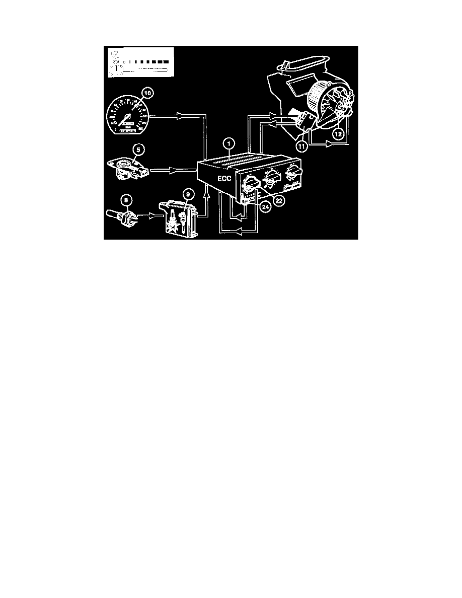
Fan Control (ECC)
The heater fan (12) speed is controlled steplessly by the power stage (11) in response to signals from the control module (1). If the fan speed control
(24) is set to automatic, the speed of the module will be influenced by the following factors:
-
The driver side temperature control (22).
The highest fan speed will be selected if the control is set to max. or min.
-
The driver side interior temperature sensor (5).
The greater the difference between the desired and actual temperatures on the drivers side, the higher the fan speed.
-
The car road speed (10).
As the speed increases, the fan speed will be reduced to maintain a constant airflow through the passenger compartment.
-
Engine temperature (8, 9).
The fan speed increases gradually as engine temperature rises when heating the passenger compartment after starting from cold.
Signals Between The Control Module And Output Stage
-
The ECC control module control signal is digital, with the length of impulses corresponding to the required fan speed. The output stage has an
electronic unit which receives signals and converts them to a fan voltage.
-
If there is no control signal or the interior fan is disabled, the output stage sends a diagnostic signal telling the control module of the fault.