
850 Turbo L5-2.3L Turbo VIN 57 B5234FT (1996)
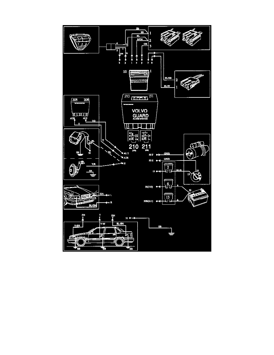
10-pin plinth on top of control module
Inhibitor Integral In Relay Plinth 210-50F (Relay/Module)
Guard Alarm I Outline Wiring Diagram
NOTE: Be careful to check the wiring diagram for the model you are actually working on as there may be some differences in designations of
connectors etc.
Guard Alarm II Outlined