
850 Turbo L5-2.3L Turbo VIN 57 B5234FT (1996)
Braking Sensor/Switch: Description and Operation
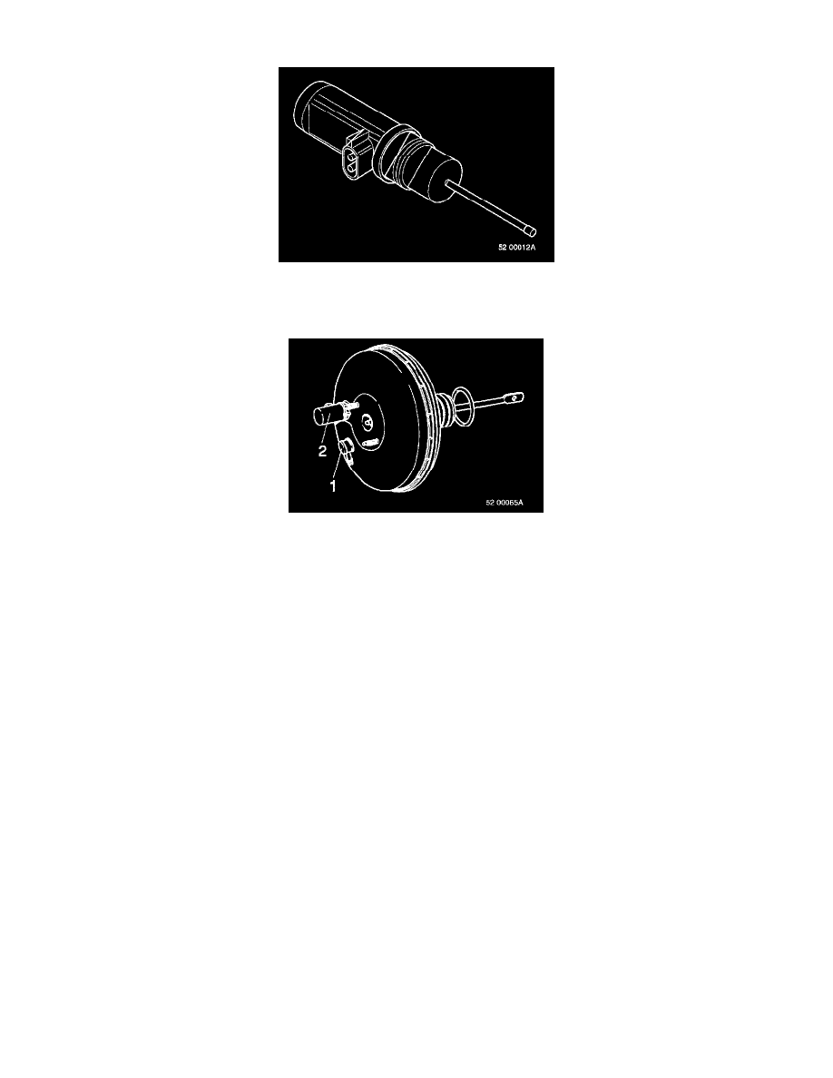
DESCRIPTION
The pedal sensor is located on the power brake booster overload relay. The pedal sensor sends a signal to the control module telling it what
position the brake pedal is in (i.e. how hard the driver is braking).
OPERATION
The control module uses the signal to indicate if there is a fault in the hydraulic system if the pedal travel is too great. The control module also
uses the signal to decide when to start and stop the hydraulic system pump so as not to affect the brake pedal position too much when the solenoid
valves are working. The pedal sensor consists of six resistors connected in series and a seventh open position read off by a sliding contact, which
means that the sensor resistance can have seven different values. With the brake pedal fully released (position 1), the sensor resistance is at
minimum. With the pedal pressed right down to the floor (position 7), the resistance is infinite. Position 7 tells the control module if the pedal is
travailing too far down, which means there may be a hydraulic fault in the system. When the brake pedal is depressed and ABS cuts in, ABS
makes the brake pedal drop slightly, which the pedal sensor records. The hydraulic pump then cuts in to keep the pedal in the right position, and
keeps working until the pedal sensor notes that the brake pedal has been pushed back up a step. This is to stop the pedal being pushed back up too
much, which would make the pedal movement uncomfortable for the driver. If the control unit finds that the pedal sensor is in position 7 while
ABS is on, it switches the hydraulic pump on and runs it for approx. 0.7 seconds. If this does not push the brake pedal back up at least one step
(e.g. because there is a leak in the system) the hydraulic pump and ABS are switched off. As power brake booster overload relay tolerances vary as
made, they are color-coded. To ensure that the pedal sensor is in the right position relative to the power brake booster overload relay, we use
different length spacers between sensor and servo. The spacers are color-coded the same as the power brake booster overload relays.