
850 Turbo L5-2.3L Turbo VIN 57 B5234FT (1996)
Wheel Speed Sensor: Description and Operation
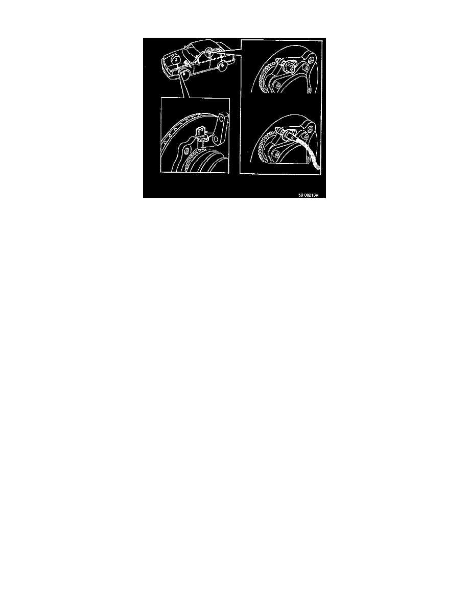
DESCRIPTION
On the front wheels, the pulse wheel is pressed onto the outer driveshaft and the wheel sensor is fitted radially in the spindle housing relative to the
pulse wheel. On the rear wheels, the pulse wheel is pressed onto the hub and the wheel sensors are located axially relative to the pulse wheel. The
rear pulse wheels are interchangeable. Both front and rear pulse wheels have 48 teeth.
OPERATION
The wheel sensors are designed to tell the control module how fast the wheels are turning. When a wheel turns, the teeth on the pulse wheel induce
a current in the wheel sensor coil. This generates an AC signal whose frequency and voltage vary with the number of teeth passing per second. The
frequency and voltage vary directly with engine speed. The induced voltage is normally approx. 300 mV AC when the wheel is turning at 1
revolution per second. By recording the frequency, the control module can calculate whether the wheel is speeding up or slowing down. If there is
a fault in any wheel sensor, ABS will cut out if in use or not cut in the first place.