
940 L4-2.3L SOHC VIN 88 B230F (1992)
The Rex I ignition is based on the fully electronically controlled Bendix ignition system with knock control. The ECU, located above the steering
column, uses electrical input signals from various devices and sensors to calculate the engine load and condition. With this information the ECU
adjusts ignition timing to provide optimum performance, economy, and the least emissions output.
The programs which enable the ECU to function are discussed below.
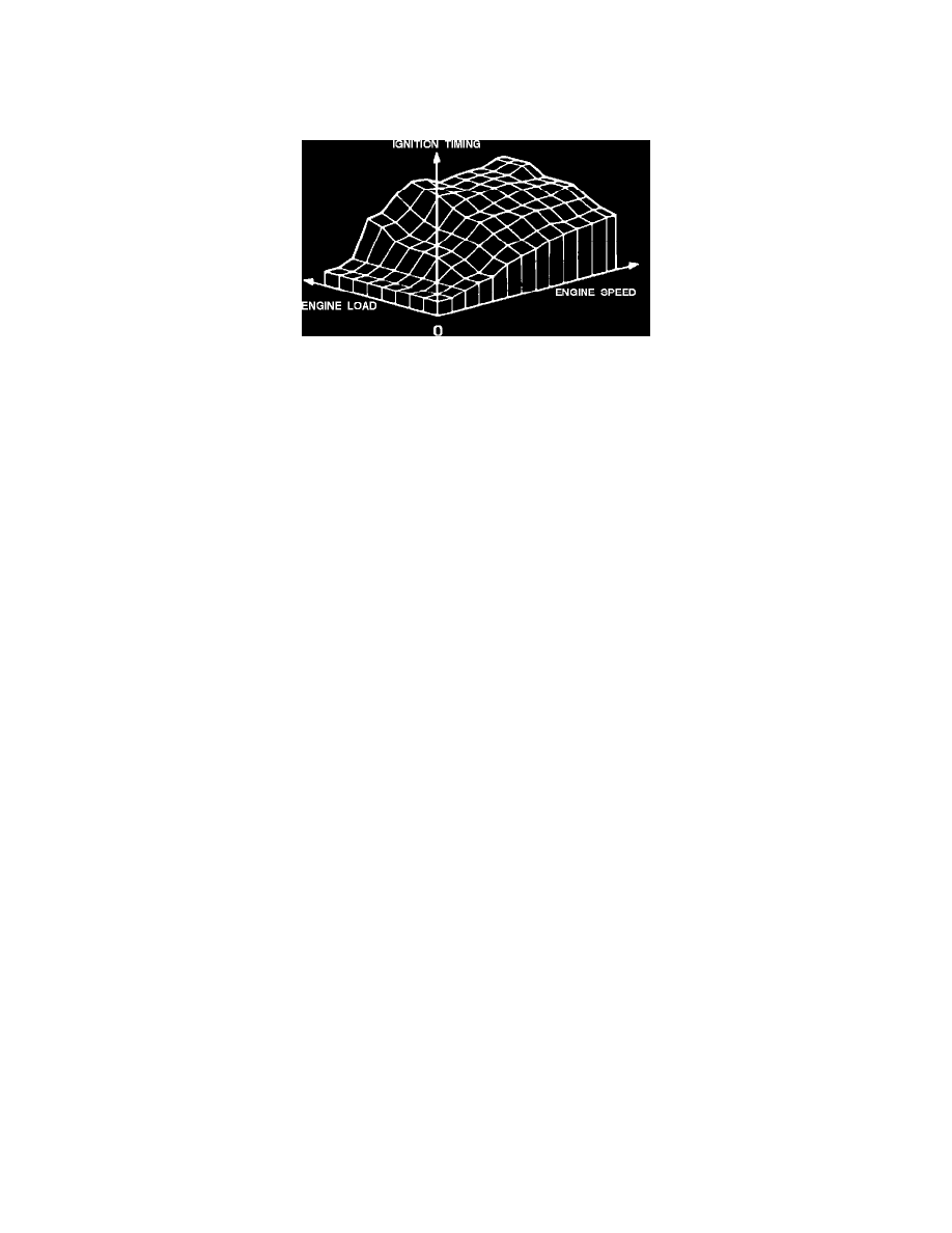
Three-Dimensional Ignition Map
TIMING PROGRAM:
The control unit is programmed with a series of specific settings for a number of defined speeds and engine loads. These settings are stored in the
ECU as an "ignition map". This means the timing can be controlled to the accuracy of a fraction of a degree. The ignition ECU will adjust the
timing according to this "ignition map" at all times under all engine loads (except engine knock).
ANTI-KNOCK PROGRAM:
Knock causes high and dangerous combustion temperatures. The ignition system will first retard the timing in approx. 3° increments (to a
maximum of 15°) to reduce knock. When the knock problem has been eliminated, the ignition ECU will advance the timing in 1° steps until the
normal setting has been restored or knock reoccurs.
STANDING CURRENT PROTECTION FUNCTION:
To avoid overheating the coil when the ignition is ON and the engine off, a separate circuit interrupts the current to the coil. The ECU uses the
engine speed and position signal to determine if the engine is running or at rest.
SELF DIAGNOSIS FUNCTION:
If the self diagnostic circuit ("on board diagnostics") in the ECU detects a fault in the ignition system, it will activate the "CHECK ENGINE" light.
By extracting the fault codes from the diagnostic socket, you can determine what component or components need further testing or replacement.
The system can store up to three fault codes.
Input devices (the ECU receives):
^ Battery supply signal (voltage).
^ Ignition switch signal.
^ Crankshaft position and speed signal.
^ Knock signal.
^ Coolant temperature signal.
^ Engine load signal from fuel injection control unit.
^ Throttle position signal.
Output devices (The ECU controls):
^ Power stage.
^ Crankshaft speed signal to the fuel injection control unit (see fuel injection ECU input devices).
^ Crankshaft position signal to the fuel injection control unit (see fuel injection ECU input devices).
^ Diagnostic socket fault information.
^ "CHECK ENGINE" light.