
940 L4-2.3L SOHC VIN 88 B230F (1992)
Removing Protective Sleeve
5.
Remove connector protective sleeve and reinstall fuse #1 for testing.
CAUTION:^ Never check connections from the front. Connectors can get damaged and worsen the problem.
^ Check connections through the holes in the connector.
^ Connection pin numbers are printed on the connector side.
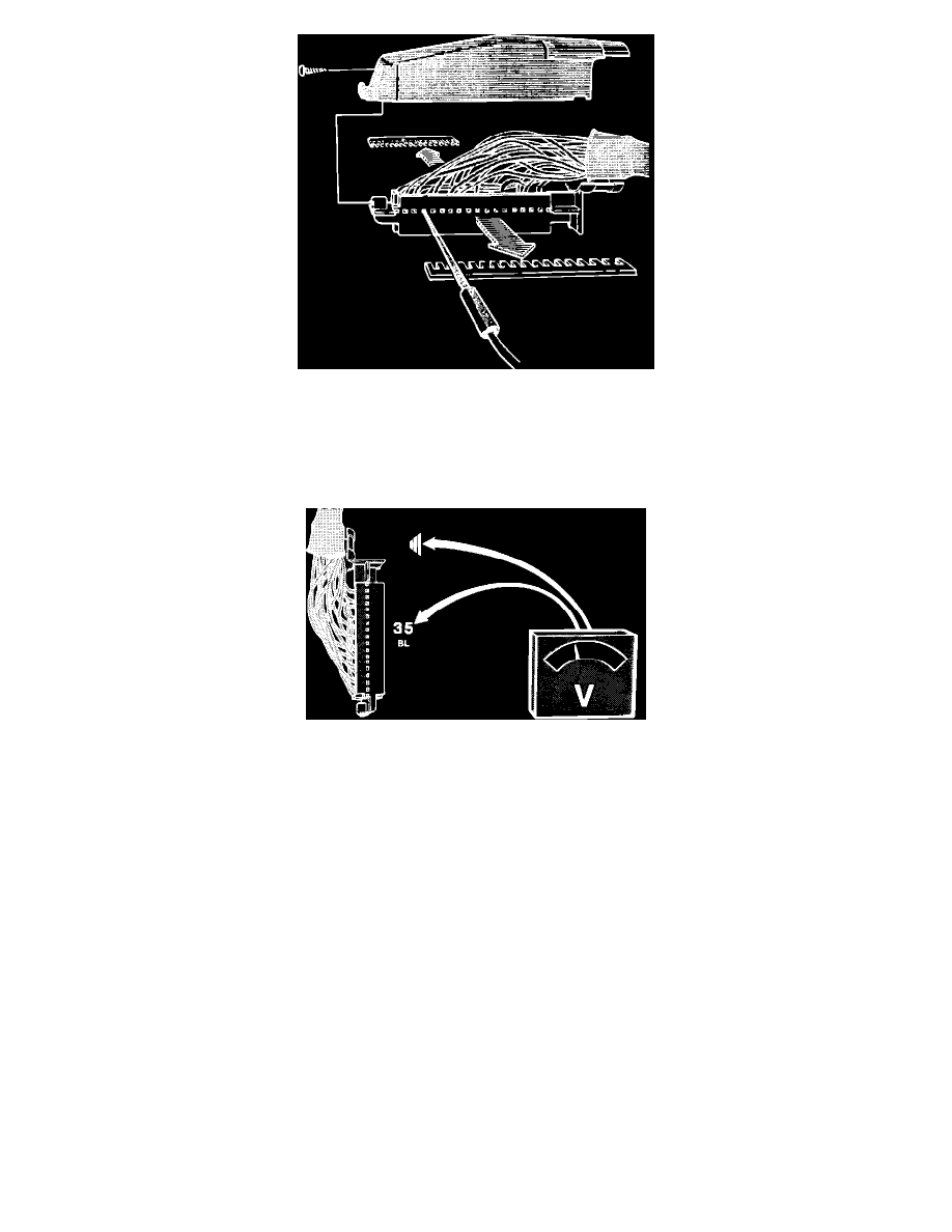
Checking Pin 35
6.
Turn ignition ON.
7.
Connect a voltmeter between pin 35 at ECU connector and ground (checking ignition switch).
Reading: 12 volts
8.
If not, check wiring, fuses #12 #13 (located behind center console ash tray) and connectors. If no fault found, replace ignition switch and retest.
9.
Crank starter motor.
Reading: 12 volts
If not, check wiring and connectors. If no fault found, replace ignition switch and retest.
10.
Turn ignition OFF.
11.
After testing, disconnect all test equipment, reconnect all connectors (including the ECU connector) and remount all panels.
Ignition ECU Input
TESTING PROCEDURE:
NOTE: While trouble shooting, always check the wiring, fuses and connectors for good condition and routing. Use the wiring diagrams found in
CHASSIS ELECTRICAL DIAGRAMS to supplement your testing efforts.