
940 L4-2.3L SOHC VIN 88 B230F (1992)
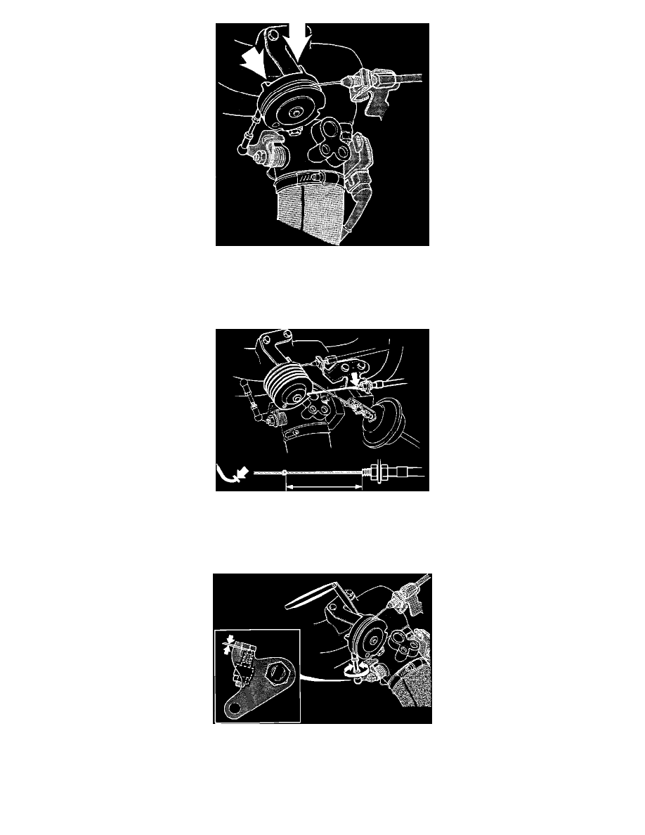
Fig. 359 ADJUST THROTTLE PULLEY AND CABLE
6.
Check for smooth operation of the control pulley and cable.
7.
Adjust the throttle cable so it is stretched at idle, but does not affect the control pulley position. At idle the control pulley should touch the stop.
8.
With the accelerator pedal fully depressed, the control pulley should touch the full throttle stop.
Fig. 362 ADJUST AUTOMATIC TRANSMISSION KICKDOWN CABLE
9.
Check the kick-down cable (if equipped) adjustment by pressing the accelerator pedal to the floor and measuring the distance between the cable
sleeve and clip. Do not operate the throttle control by hand, it can give you a wrong reading. Measurement should read 50.4 - 52.6 mm (1.98 - 2.07
in), adjust as necessary.
Fig. 360 CONNECT AND ADJUST LINK ROD
10.
Connect the link rod.
11.
Place a 1 mm (0.04 in) feeler gauge between the control pulley and idle speed stop. Clearance between the lower adjustment screw and the end
stop should now be 0.1 mm (0.004 in). Adjust link rod as needed.