
940 L4-2.3L SOHC VIN 88 B230F (1992)
**
If there are only three valves listed it means there isn't a right rear valve and therefore no wire in Pin 19. If a wire exists in Pin 19 it will mean
the system has four solenoid valves.
***
Not all Bosch ABS 2 have a Solenoid valve on the right rear wheel. This does not mean that if a system has only three solenoid valves that it
will only have three wheel speed sensors. These differences are sorted out in the chart.
****
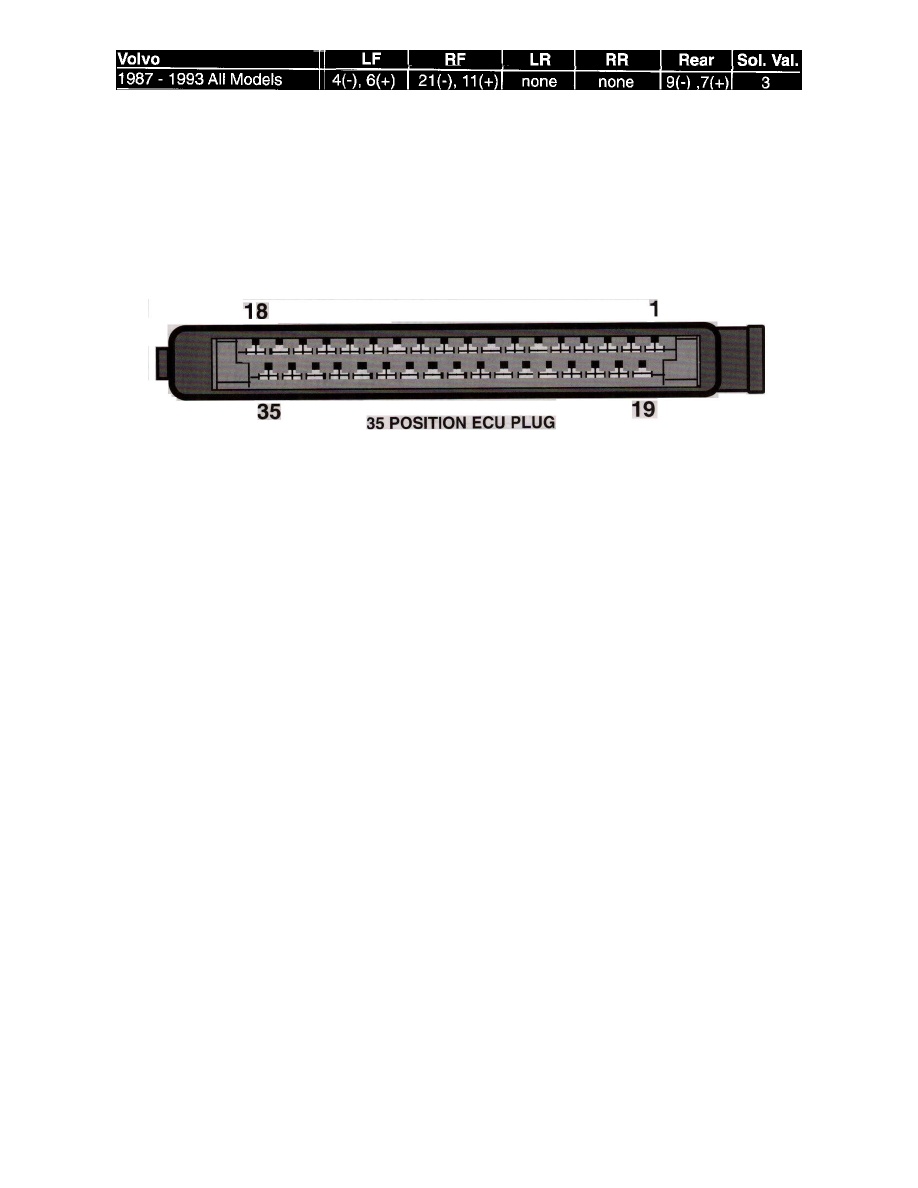
Not all Bosch ABS 2 have a wheel speed sensor on the right rear wheel. Systems that have only three wheel speed sensors have the rear sensor
mounted in the differential housing. The easiest way to determine how the wheel speed sensors are wired is to inspect the 35 Pin plug and see
what contacts are used for in system being tested.
Teves - ABS
35 Position ECU Plug
Connector View
System
Teves ABS
Location
Terminal ID
1 - Ground
2 - Ignition Switch
3 - Main Power Relay
4 - Wheel Speed Sensor Right Rear (-)
5 - Wheel Speed Sensor Left Front (-)
6 - Wheel Speed Sensor Left Rear (-)
7 - Wheel Speed Sensor Right Front (-)
8 - Main Power Relay Control
9 - Fluid Level Switch
10 - Fluid Pressure Switch
11 - Solenoid Valve Ground
12 - Brake Light (NC Scorpio)
13 - NC
14 - Pump Relay Monitor (NC Ford, GM)
15 - Inlet Solenoid Valve (Right Front)
16 - Outlet Solenoid Valve (Left Front)
17 - Inlet Solenoid Valve (Rear)
18 - Main Hydraulic Solenoid Valve
19 - Ignition Switch (Scorpio only)
20 - Main Power Relay
21 - NC
22 - Wheel Speed Sensor Right Rear (+)
23 - Wheel Speed Sensor Lett Front (+)
24 - Wheel Speed Sensor Left Rear (+)
25 - Wheel Speed Sensor Right Front (+)
26 - NC
27 - ABS Warning Light
28 - NC
29 - NC
30 - NC
31 - NC