
940 L4-2.3L SOHC VIN 88 B230F (1992)
Fuel Injection System And Components
PURPOSE
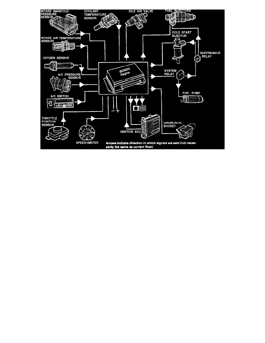
The Electronic Control Unit (ECU), located in passenger side kick panel, has a microprocessor that receives signals from various input devices
regarding engine operating conditions. This information will be evaluated in relation to pre-programmed values and it calculates the optimal
injector frequency (opening duration) to provide optimal air/fuel mixture, performance, driveability and emissions output.
Input devices (the ECU receives):
^ Battery supply signal (voltage).
^ Ignition switch signal.
^ Intake manifold pressure sensor signal.
^ Intake air temperature sensor.
^ Oxygen sensor (lambda sond) signal.
^ Crankshaft speed signal from the ignition control unit.
^ Speedometer signal.
^ Crankshaft position signal from the ignition control unit.
^ Coolant temperature signal.
^ Throttle position signal.
^ Gear selector signal (automatic trans. only).
^ A/C switch signal.
^ A/C pressure sensor signal.
Output devices (The ECU controls):
^ System relay ground.
^ Suppressor relay by controlling the system relay.
^ Fuel injector ground.
^ Cold start injector ground.
^ Idle air valve.
^ Engine load signal to the ignition system control unit (see ignition ECU input devices).
^ Shift indicator light (manual trans. only).
^ Diagnostic socket fault information.
^ "CHECK ENGINE" light.
START-UP PROGRAM:
The cold engine start-up program provides for two injection periods per revolution. When the engine reaches operating temperature, the ECU uses
only one injection period per revolution.