
940 L4-2.3L SOHC VIN 88 B230F (1992)
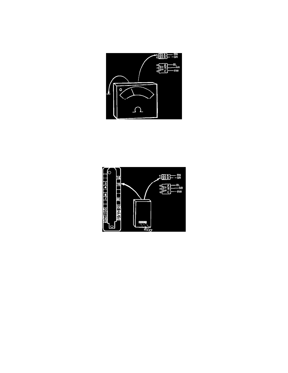
Checking "B" Terminal At Three Wire Connector
18.
Measure resistance between terminal "B" at three wire connector and ground.
Reading: no more then 0.1 ohm
If reading is to high, clean or replace ground connection or wire.
Checking "A" Terminal At Two Wire Connector
19.
Measure resistance between terminal "A" at two wire connector and ground.
Reading: no more then 0.1 ohm
If reading is to high, clean or replace ground connection or wire.
Checking "B" Terminal At Two Wire Connector
20.
Connect a buzzer between terminal "B" at two wire connector and pin 16 at ignition ECU connector. Buzzer should sound if wire is intact. If not,
repair wire or connectors.
21.
If engine will not start after all faults have been repaired or no fault has been found in all of the above listed tests, problem lies in the ignition
control ECU or power stage. Verification can only be made by replacing the ECU or power stage with a known good unit.
22.
After testing, disconnect all test equipment, remount the ignition coil, reconnect all connectors (including the ECU connector) and remount all
panels.