
940 L4-2.3L SOHC VIN 88 B230F (1992)
Ignition Control Module: Testing and Inspection
Bosch
TESTING PROCEDURE:
NOTE: While trouble shooting, always check the wiring, fuses and connectors for good condition and routing. Use the wiring diagrams found in
CHASSIS ELECTRICAL DIAGRAMS to supplement your testing efforts.
Accessing Power Stage
1.
Turn ignition OFF and access the power stage by removing the air filter housing top.
Disconnecting Power Stage
2.
Disconnect the power stage connector.
IMPORTANT:Ignition must be OFF when connecting or disconnecting power stage connector.
3.
Remove rubber boot from connector to uncover pins. Always test the pins from the back. Never test pins from the front, damage may occur.
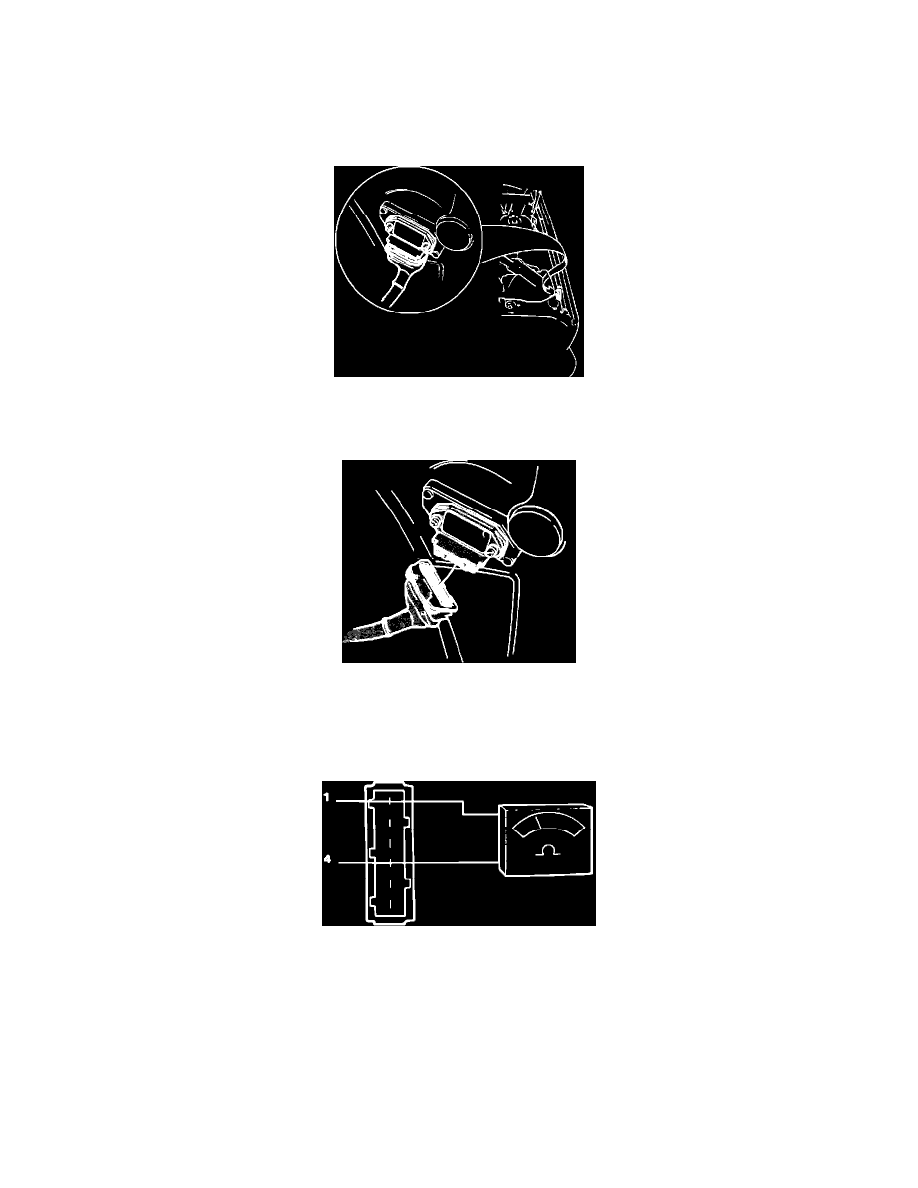
Checking Pin 1 And 4
4.
Check ignition coil primary winding by connecting an ohmmeter between pin 1 (red-white) and 4 (blue).
Reading: 0.6 - 1.0 ohm