
940 L4-2.3L SOHC VIN 88 B230F (1992)
Removing Protective Sleeve
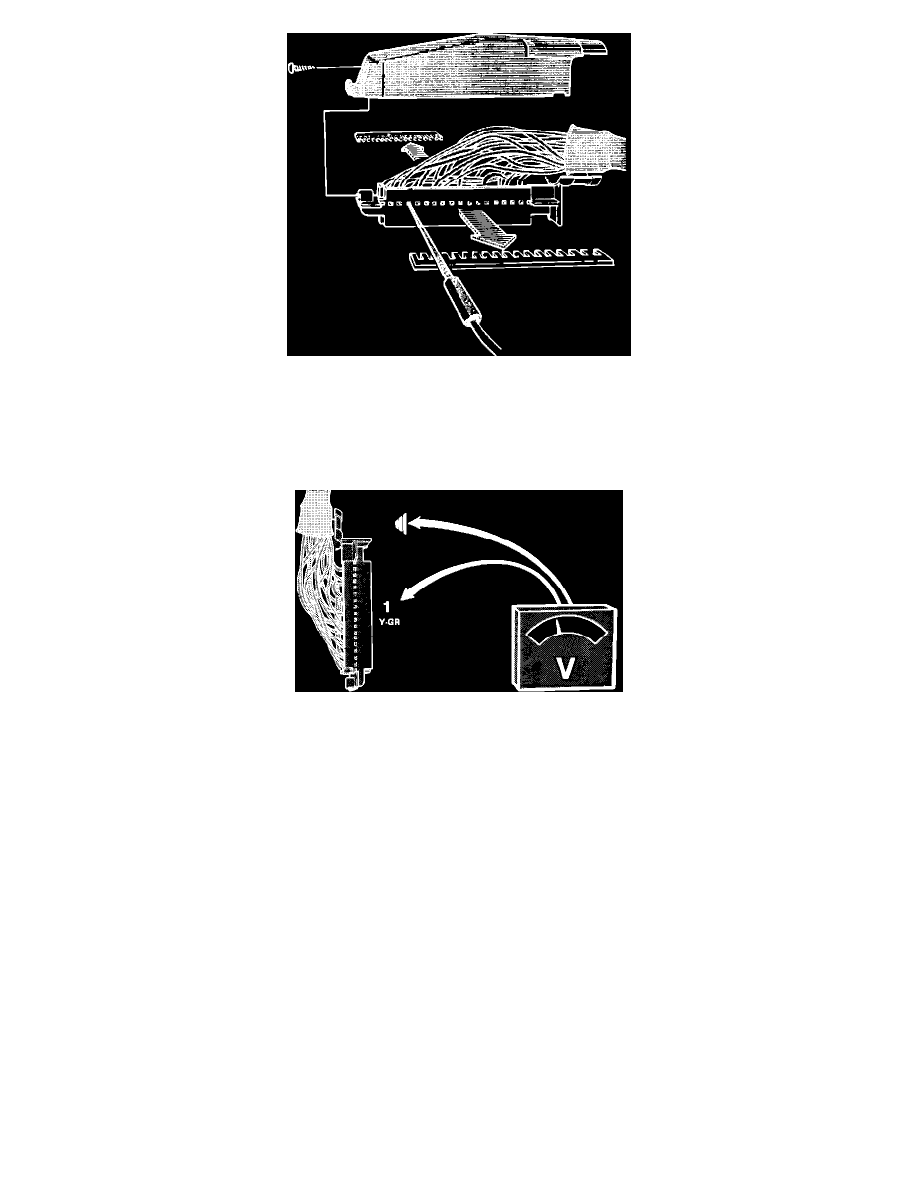
5.
Remove connector protective sleeve and reinstall fuse #1 for testing.
CAUTION:^ Never check connections from the front. Connectors can get damaged and worsen the problem.
^ Check connections through the holes in the connector.
^ Connection pin numbers are printed on the connector side.
Checking Pin 1
6.
Check RPM sensor lead from ignition ECU by connecting a voltmeter from pin 1 on fuel injection ECU connector to ground.
7.
Turn ignition ON.
Reading: approx. 12 volts
8.
If reading is different, check wiring and connections. Fix as necessary. If wiring and connections are O.K., check ignition ECU (see ON-BOARD
DIAGNOSTICS).
9.
Turn ignition OFF.
10.
Disconnect the test equipment. Remove the #1 fuse and reconnect the ECU and all other connectors, install the kick panel and glove compartment.
Ensure that the rubber seal in the ECU connector is installed before it is connected to the unit.
11.
Reinstall the #1 fuse.
Bosch
The following testing procedure checks only the crankshaft position/speed signal from the ignition ECU, not the sensor itself. For crankshaft
position/speed sensor test see FOR IGNITION ECU.
TESTING PROCEDURE:
NOTE: While trouble shooting, always check the wiring, fuses and connectors for good condition and routing. Use the wiring diagrams found in
SCHEMATIC DIAGRAMS to supplement your testing efforts.