
940 L4-2.3L SOHC VIN 88 B230F (1992)
Knock Sensor: Description and Operation
Bendix
Knock Sensor
Used by the fuel injection and ignition ECU:
PURPOSE AND LOCATION
The knock signal is generated by the knock sensor located on the left side of the engine block between number 2 and three cylinders. When engine
knock is detected, the knock sensor develops a voltage which the ignition ECU registers. This signal is then sent from the ignition ECU to the fuel
injection ECU. The ECU's then take appropriate action by retarding the ignition timing and enriching the air/fuel mixture if necessary.
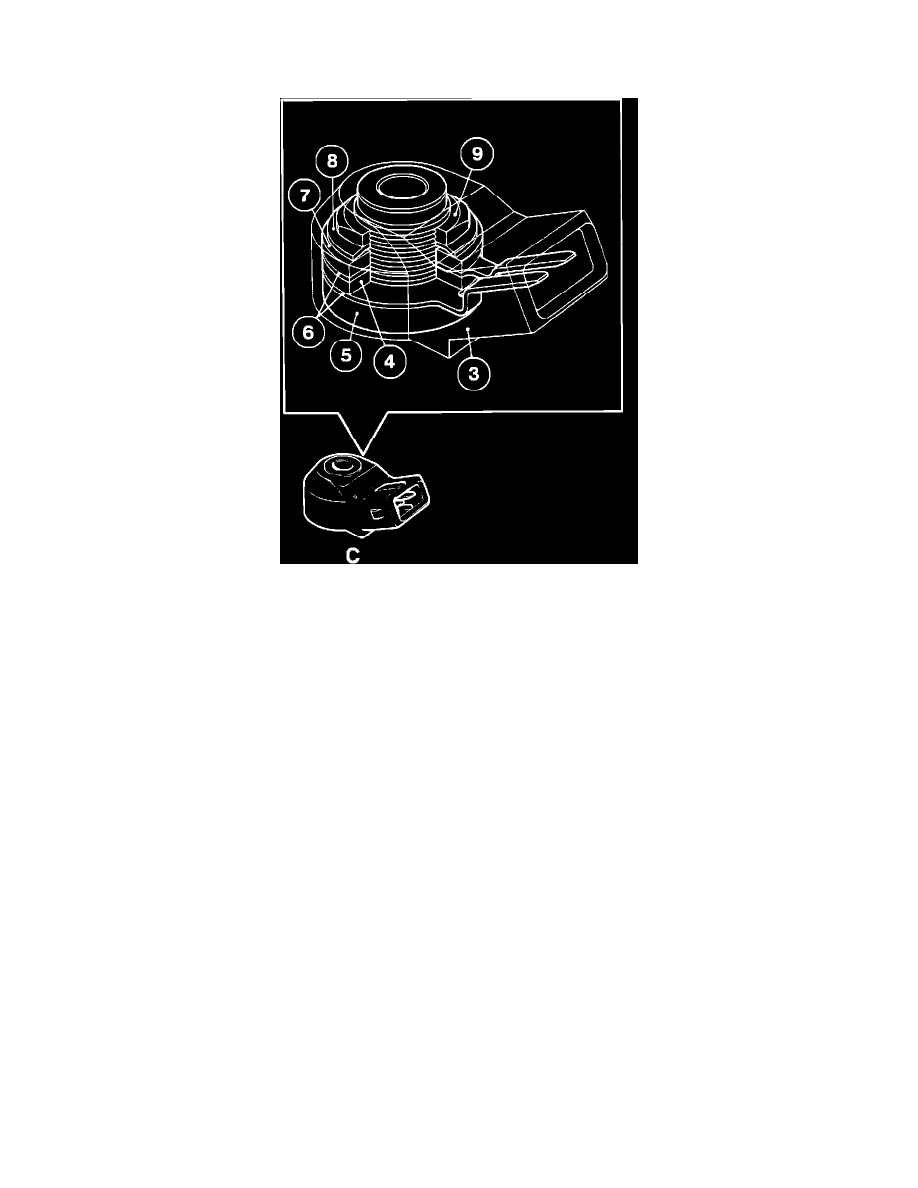
CONSTRUCTION
The knock sensor (C) consists of a housing (3) a piezoelectric crystal (4) mounted on a threaded sleeve (5) between two connector strips (6). One
side of the assembly is fitted with a damping weight (7) and spring washer (8) secured by a nut (9).
OPERATION
Mounted on the engine block, the sensor is subjected to the vibrations generated by knock. The vibrations cause a small distortion on the surface
of the piezoelectric crystal, which consequently generates a small voltage. This voltage is read by the ignition ECU.
SIGNAL
The signal from the sensor is a continuous, but variable voltage. The frequency of the voltage is dependent on the amount of engine knock. The
signal is fed into the ignition ECU which computes it as a reference value. This reference value is then forwarded to the fuel injection ECU.