
940 L4-2.3L SOHC VIN 88 B230F (1992)
Crash Sensor And Standby Power Unit
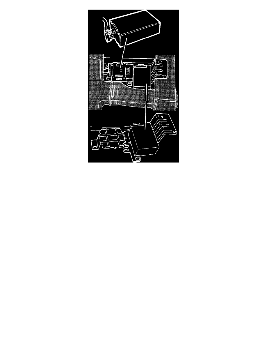
4.
Remove tape from standby power unit, then disconnect electrical connector and clip.
5.
Remove crash sensor retaining screws and release cable clamp.
6.
Remove crash sensor and wiring harness.
7.
Reverse procedure to install, noting the following:
a. Use original screws. Torque to 8 ft. lbs.
b. Crash sensor connector is held in place by a fixture which is part of the body where it bolts. Place carefully to avoid damaging connector.
c. Check for fault codes as described under DIAGNOSIS AND TESTING PROCEDURES/TESTING PROCEDURES/FAULT TRACING
(SRS) SYSTEM.