
940 L4-2320cc 2.3L DOHC VIN 89 B234F FI (1991)
Engine Control Module: Description and Operation
Ignition
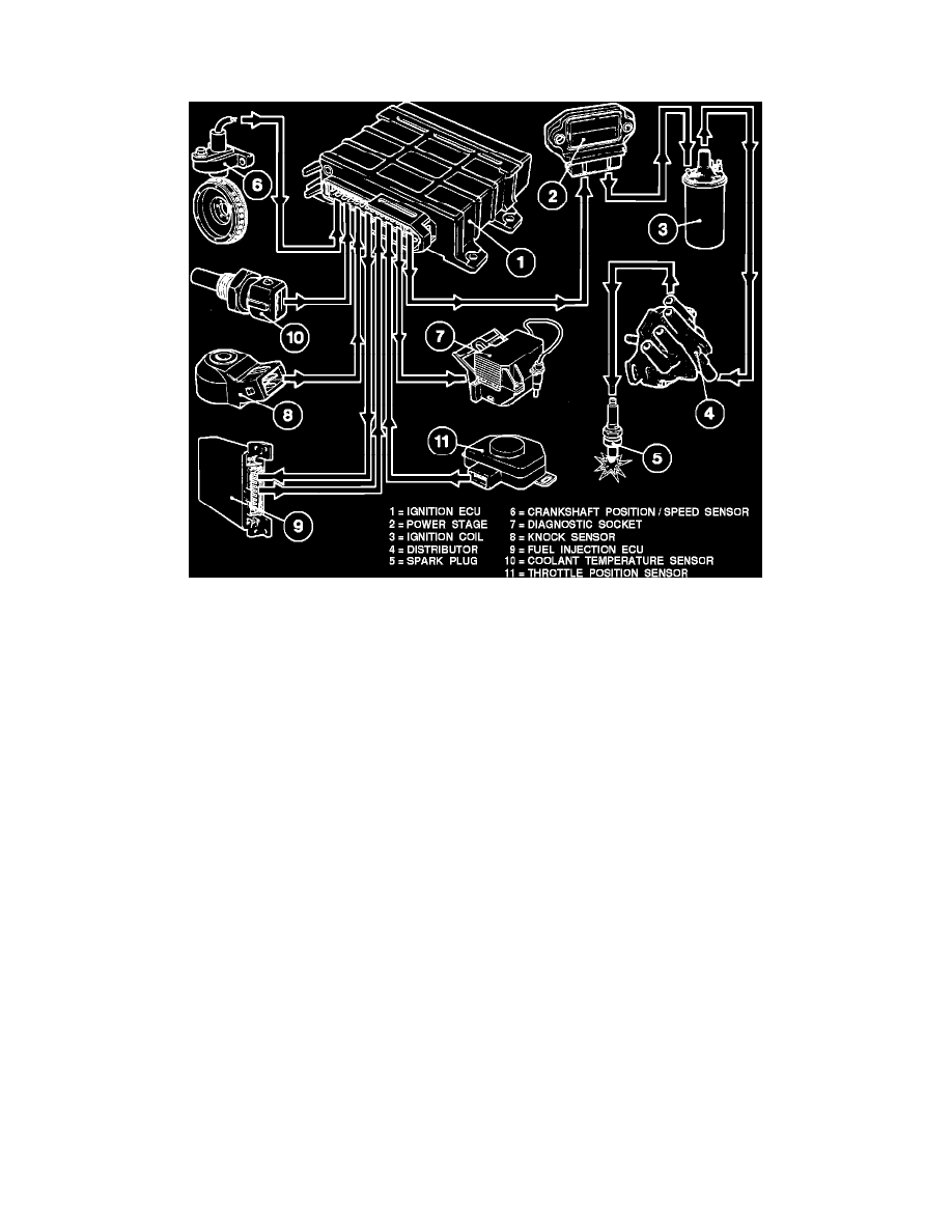
Ignition System Schematic
This ignition is based on the fully electronically controlled Bosch ignition system with knock control (EZ-K). The ECU (located under instrument panel
above gas pedal to the right) uses electrical input signals from various devices and sensors to calculate the engine load and condition. With this
information the ECU will adjust the ignition timing to provide optimal performance, driveability and emissions output.
Input devices (the ECU receives):
^ Battery supply signal (voltage).
^ Ignition switch signal.
^ Crankshaft position and speed signal.
^ Knock signal.
^ Coolant temperature signal.
^ Air mass meter signal from fuel injection control unit.
^ Throttle position signal.
Output devices (The ECU controls):
^ Power stage.
^ Crankshaft speed signal to the fuel injection control unit (fuel injection ECU input device).
^ Crankshaft position signal to the fuel injection control unit (fuel injection ECU input device).
^ Knock signal to the fuel injection control unit (fuel injection ECU input device).
^ Diagnostic socket fault information.
^ "CHECK ENGINE" light.