
Testing and Inspection for Fuel Injection ECU Input
Ignition Switch: Testing and Inspection
Ignition ECU Input
TESTING PROCEDURE:
NOTE: While trouble shooting, always check the wiring, fuses and connectors for good condition and routing. Use the wiring diagrams found in
CHASSIS ELECTRICAL DIAGRAMS to supplement your testing efforts.
Accessing Ignition ECU Connector
1.
Turn ignition OFF.
2.
Access ignition ECU by removing the panel under left hand side of instrument panel.
3.
Remove ECU connector by pushing out the catch and folding out the wire cluster.
4.
Check ignition ECU ground connections at intake manifold. They should make good contact.
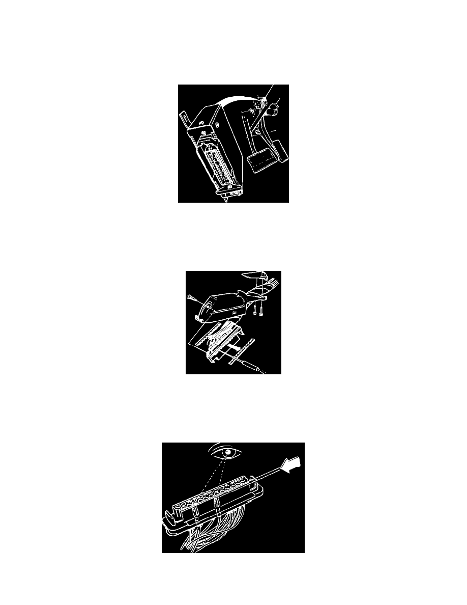
Removing Protective Cover
5.
Remove connector protective sleeve.
IMPORTANT:^ Never check connections from the front. Connectors can get damaged and worsen the problem.
^ Check connections through the holes in the connector.
^ Connection pin numbers are printed on the connector side.
Checking Terminal Pins