
940 L4-2320cc 2.3L SOHC Turbo VIN 87 B230FT (1992)
Data Link Connector: Description and Operation
Fuel Injection
Diagnostic Socket Location
PURPOSE AND LOCATION
The fuel injection ECU has a self diagnostic and function test system. These are combined with the diagnostic and function test system of the
ignition ECU.
The diagnostic system of the fuel injection ECU is capable of detecting 17 faults and storing three different codes (California vehicles can store all
17 fault codes) in its memory. The ECU continuously monitors the following functions during driving:
^ Control unit internal functions
^ Oxygen sensor (lambda sond) control
^ Coolant temperature sensor
^ Air mass meter
^ Battery voltage
^ Throttle switch
^ Engine speed and position signal (from ignition ECU)
^ Speedometer signal
^ Knock sensor signal (from ignition ECU)
^ Idle valve operation
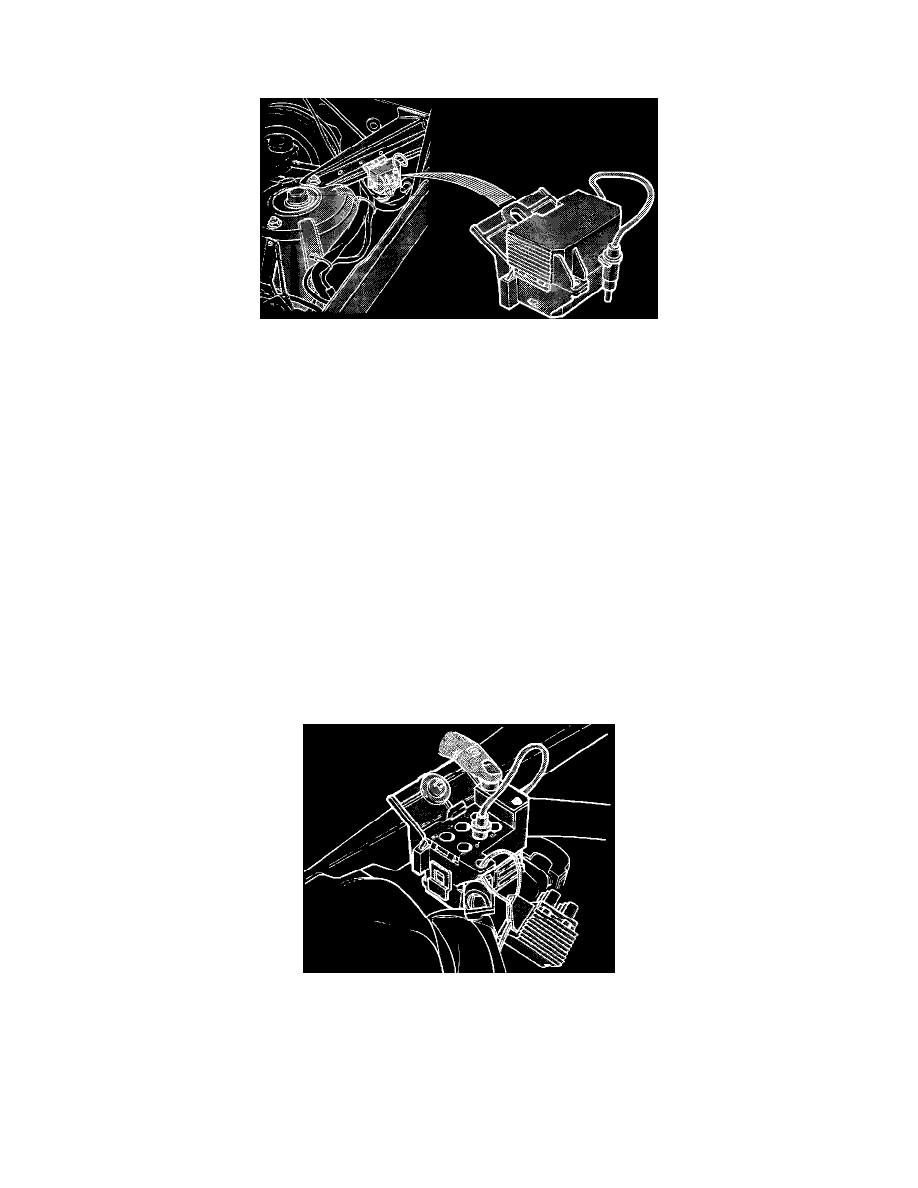
To check the fault code memory or a component, you must access the diagnostic socket located in the engine compartment behind the left
suspension tower.
Diagnostic Socket Description
FUNCTION
This diagnostic socket is used for communication with the diagnostic functions in the fuel injection and ignition ECU.
The diagnostic socket consists of a button, an LED and a selector cable. For fault tracing on the fuel injection system, the selector cable is placed
in output #2. By pressing the button once, twice or three times (depending on control function required), the fuel injection ECU is accessed.