
940 L4-2320cc 2.3L SOHC VIN 83 B230FD (1993)
2.
Access fuel injection ECU by removing the passenger side kick panel and glove compartment.
3.
Check fuel injection ECU ground connections. They should make good contact and fit tight.
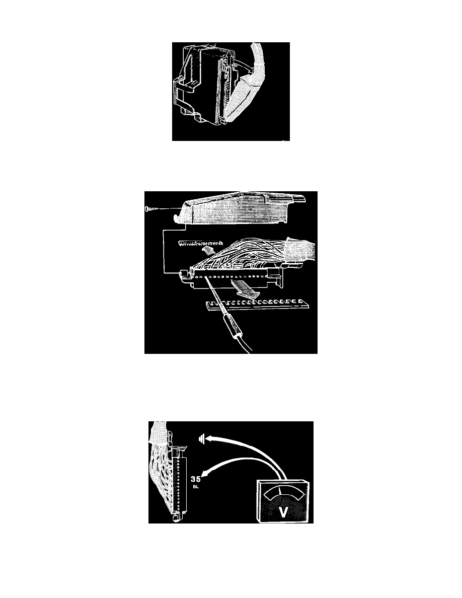
Removing ECU Connector
4.
Remove fuse #1 (located in central electric unit behind ash tray) to interrupt the power supply. Then remove the ECU connector by pressing up the
latch and folding out the wire cluster.
Removing Protective Sleeve
5.
Remove connector protective sleeve and reinstall fuse #1 for testing.
CAUTION:^ Never check connections from the front. Connectors can get damaged and worsen the problem.
^ Check connections through the holes in the connector.
^ Connection pin numbers are printed on the connector side.
Checking Pin 35
6.
Turn ignition ON.
7.
Connect a voltmeter between pin 35 at ECU connector and ground (checking ignition switch).