
940 L4-2320cc 2.3L SOHC VIN 83 B230FD (1993)
Checking Ground Connections
11.
Connect an ohmmeter between pin 5 and ground.
Reading: 0 ohm
12.
If not, check wiring and fix as necessary.
13.
Then connect the ohmmeter between pin 17 and ground.
Reading: 0 ohm
14.
If not, check wiring and fix as necessary.
15.
Then connect the ohmmeter between pin 19 and ground.
Reading: 0 ohm
16.
If not, check wiring and fix as necessary.
17.
Then connect the ohmmeter between pin 29 and ground.
Reading: 0 ohm
18.
If not, check wiring and fix as necessary.
19.
Disconnect the test equipment. Remove the #1 fuse and reconnect the ECU and all other connectors, install the kick panel and glove compartment.
Ensure that the rubber seal in the ECU connector is installed before it is connected to the unit.
20.
Reinstall the #1 fuse.
21.
The previous tests eliminate any power supply or ECU ground problems. If an ECU fault is suspected, go by the FLOW OF DIAGNOSIS or see
step 22.
22.
To find the problem, you can test every input and output device. If no faults are found and all wiring, connectors, fuses and the battery are in good
condition, replace and retest ECU with known good unit.
Bendix
TESTING PROCEDURE:
NOTE: While trouble shooting, always check the wiring, fuses and connectors for good condition and routing. Use the wiring diagrams found in
CHASSIS ELECTRICAL DIAGRAMS to supplement your testing efforts.
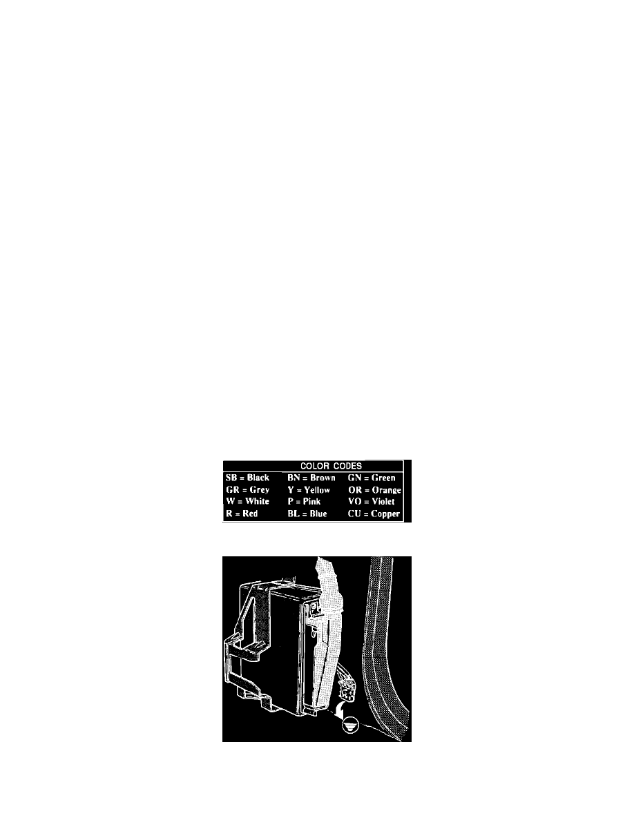
Color Code Legend
Checking ECU Ground Connections
1.
Turn ignition OFF.