
940 L4-2320cc 2.3L SOHC VIN 83 B230FD (1993)
Checking Terminal Pins
6.
Check that terminal contacts have been pushed down evenly in connector.
7.
If any connectors have been pushed down to far, poor connection may result.
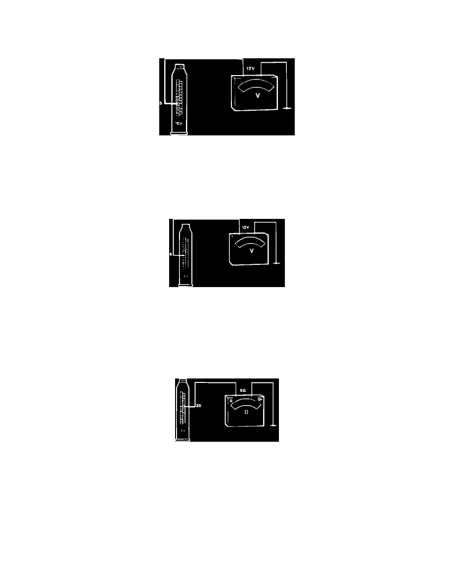
Checking Battery Supply
8.
Check main power supply by connecting a voltmeter between pin 5 (brown) in ECU connector and ground.
Reading: approx. 12 volts
9.
If no voltage registers, check wire between ECU and fuse-box located behind the center console ash tray. Check fuse #1 and wiring to battery
(incl. battery terminals). Repair as necessary.
Checking Pin 6
10.
Turn ignition ON.
11.
Connect a voltmeter between pin 6 (blue) at ECU connector and ground (checking ignition switch).
Reading: approx. 12 volts
12.
If not, check wiring and connectors. If no fault found, replace ignition switch and retest.
13.
Turn ignition OFF.
Checking Pin 20
14.
Connect an ohmmeter between pin 20 (brown) and ground.
Reading: 0 ohm
15.
If not, check wiring and fix as necessary.
16.
After testing, disconnect all test equipment, reconnect all connectors (including the ECU connector) and remount all panels.
17.
The previous tests eliminate any power supply or ECU ground problems. If an ECU fault is suspected, go by the FLOW OF DIAGNOSIS or see
next step.
18.
To find the problem, you can test every input and output device. If no faults are found and all wiring, connectors, fuses and the battery are in good
condition, replace ECU and retest with known good unit.
Bosch