
940 SE L4-2320cc 2.3L SOHC Turbo VIN 87 B230FT (1991)
Antitheft and Alarm Systems: Testing and Inspection
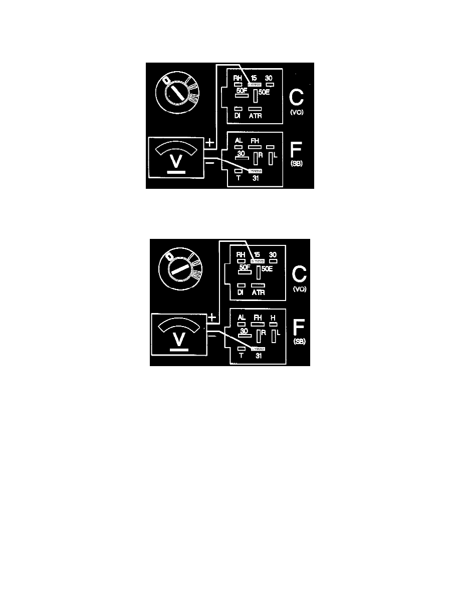
Checking the ignition feed
Measurement A:
-
Ignition off.
-
Connect a voltmeter between item 15 and item 31 on the alarm relay base. The voltmeter should show 0 V.
Measurement B:
-
Ignition on.
-
Connect the voltmeter again between item 15 and item 31 on the alarm relay base. The voltmeter should show battery voltage.
If both readings are correct:
-
Continue with step N5.
If measurement A deviates:
There is a short to ground in the lead between the ignition lock and the alarm relay base item 15.
-
Rectify the fault or renew the lead.
Replace the alarm control module.
If measurement B deviates:
There is a break in the lead between the ignition lock item 15A and the alarm relay base item 15, or the fuse in the fusebox may be blown.
-
fuse 12
-
Rectify the fault or renew the lead.
Replace the alarm control module.