
940 SE L4-2320cc 2.3L SOHC Turbo VIN 87 B230FT (1991)
Reading: 0 ohm
15.
If not, repair fault in wiring or connectors.
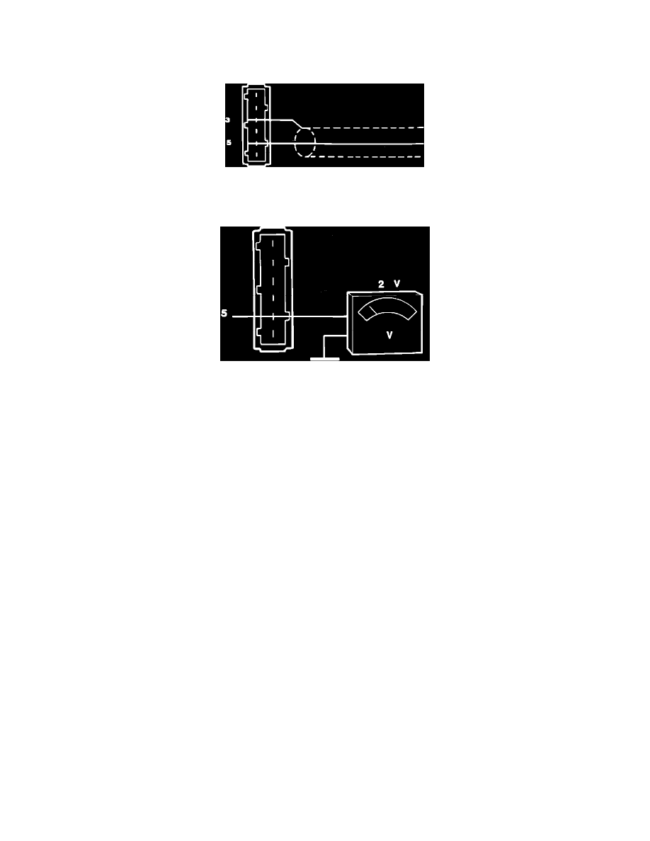
Checking Pin 3 And 5
16.
Check that wire screen is properly connected to terminal 3.
Checking Terminal #5
17.
Disconnect leads from ignition coil terminal 1 (red-white) and 15 (blue).
18.
Connect voltmeter between terminal 5 at power stage connector and ground.
19.
Run starter motor.
Reading: approx. 2 volts
a. If reading is correct, turn ignition OFF, disconnect all test equipment and reconnect all connectors. Run starter motor, if no spark is available
at ignition coil replace and retest with new power stage.
b. If reading is incorrect, power stage is missing the ECU signal. Check wiring from terminal 5 (gray) to ECU. Repair as needed. If no fault can
be found, ECU or another input component is faulty. Check all components and replace as needed.
20.
Turn ignition OFF
21.
After testing, disconnect all test equipment, reconnect all connectors and place rubber boot back over connector to cover pins.