
960 L6-3.0L VIN 95 B6304F (1993)
Hydraulic Control Assembly - Antilock Brakes: Description and Operation
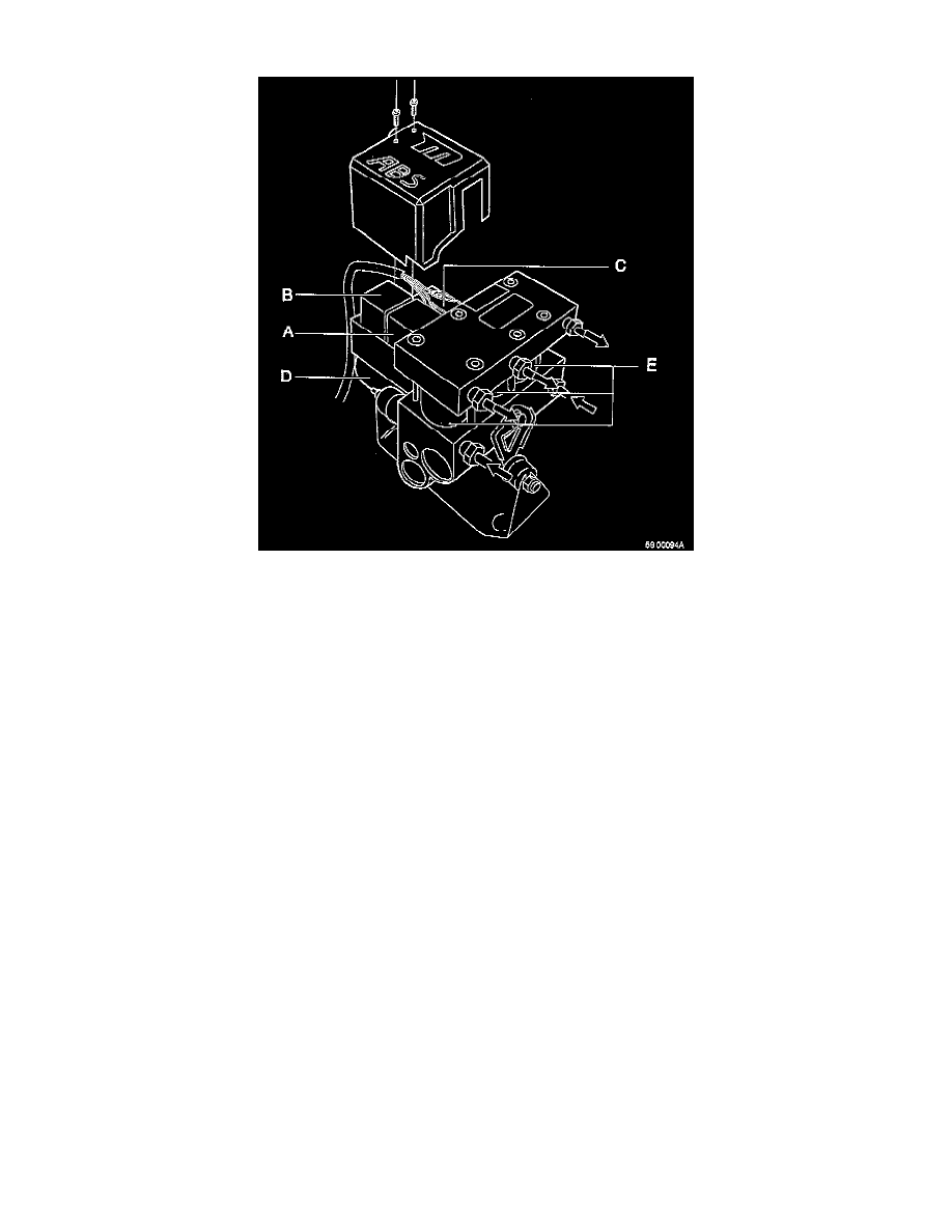
DESCRIPTION
The hydraulic modulator processes the signals from the control module and helps maintain the right pressure in the brake calipers at all times. The
hydraulic modulator comprises: valve relay (A), pump motor relay (B), connector (C), pump and motor in a single unit (D) and three valves (E).
The brake fluid reservoir and master cylinder are separate from the hydraulic modulator. The brake pipe connections are punched into the valve
block as follows:
valve, outlet, front left-hand wheel: LF
valve, outlet, front right-hand wheel: RF
valve outlet, rear wheels: RR
front inlet: F
rear inlet: R
NOTE: These designations are also used in the diagnosis/fault-tracing sections to indicate individual wheels, sensors etc.
OPERATION
If a wheel starts to lock, the pressure in the locked wheel brake circuit is reduced (both calipers for the rear brakes) and the integral motor control
pump pumps brake fluid back from the brake caliper to the master cylinder.