
960 L6-3.0L VIN 95 B6304F (1993)
Knock Sensor: Description and Operation
Knock Sensor
PURPOSE
The knock sensor generates a "knock" signal for the ECU. When engine knock is detected, the knock sensor develops a voltage which the ECU
registers. The ECU takes appropriate action by retarding the ignition timing and enriching the air/fuel mixture if necessary.
LOCATION
Two knock sensors are located on the left side of the engine block; one near cylinder 2, the other near cylinder 5.
CONSTRUCTION
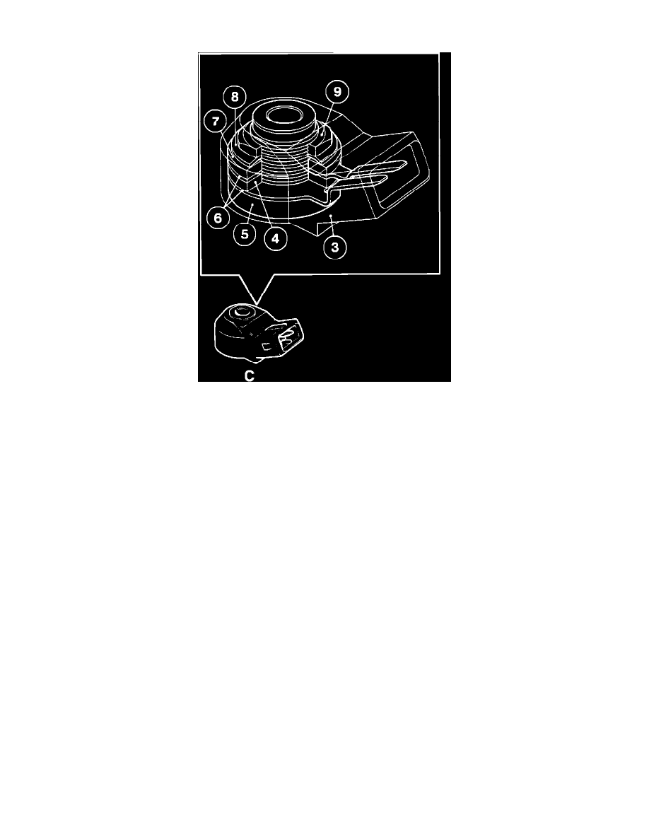
The knock sensor (C) consists of a housing (3) a piezoelectric crystal (4) mounted on a threaded sleeve (5) between two connector strips (6). One
side of the assembly is fitted with a damping weight (7) and spring washer (8) secured by a nut (9).
OPERATION
Mounted on the engine block, each sensor is subjected to the vibrations generated by knock. The vibrations cause a small distortion on the surface
of the piezoelectric crystal, which consequently generates a small voltage. This voltage is read by the ECU.
SIGNAL
The signal from each sensor is a continuous, but variable voltage. The frequency of the voltage is dependent on the amount of engine knock. The
signal is fed into the ECU which computes it as a reference value.