
960 L6-3.0L VIN 95 B6304F (1993)
Control Arm Bushing: Service and Repair
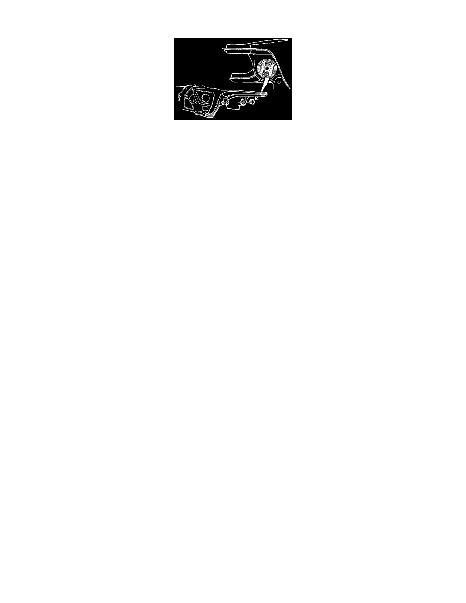
Fig. 8 Upper Control Arm Bushing Orientation
UPPER
1.
Raise and support vehicle, remove wheel, then the caliper and hang from spring with wire.
2.
Disconnect support arm, lower control arm, track rod and upper control arm from wheel bearing housing. Use a small puller and a 12 mm x 50 mm
bolt to disconnect track rod from housing. Retain spacers located between upper control arm and wheel bearing housing.
3.
Remove nut securing control arm to rear axle member at rear, bolt and nut securing control arm to rear axle member at front, then the control arm.
4.
Mount control arm in a vise, then use a chisel to pry up edge of outer bushing.
5.
Mount control arm in a hydraulic press using two V-blocks as counterholds, then press out outer bushing using drift 5345.
6.
Press in new outer bushing using drift 5090, counterhold 5087 and a hydraulic press.
7.
Mount control arm in a vise, then use a chisel to pry up edge of inner front bushing.
8.
Mount control arm in a hydraulic press, then press out inner front bushing using drift 5345, counterhold 5343 and drift 5347.
9.
Press in new inner front bushing using drift 2731, counterhold 2904 and a hydraulic press.
10.
If replacing left inner rear bushing, lower support arm slightly.
11.
Press out inner rear bushing using press tool 5343.
12.
Press in new inner rear bushing using press tool 5353. Note orientation of bushing, Fig. 8.
13.
Install control arm, bolt and nut securing control arm to rear axle member, spacers between upper control arm and wheel bearing housing, then the
nut securing control arm to wheel bearing housing.
14.
Pull top of wheel bearing housing outward while tightening upper control arm nut to specifications.
15.
Pull wheel bearing housing outward and insert lower control arm, then pull wheel bearing housing inward toward differential while tightening
control arm nut to specifications.
16.
Connect support arm and track rod, then install brake caliper and wheel.
LOWER
1.
Raise and support vehicle, remove wheel, then the caliper and hang from spring with wire.
2.
Remove brake disc and handbrake pads, then disconnect handbrake cable.
3.
Disconnect support arm and lower control arm from wheel bearing housing and lower control arm from rear axle member, then remove lower
control arm.
4.
Use a small puller and a 12 mm x 50 mm bolt to disconnect track rod from housing.
5.
Remove hub nut and nut securing upper support arm to wheel bearing housing, then the hub assembly. Retain spacers between upper support
arm and wheel bearing housing.
6.
Replace control rod bushing using a 1.318-1.358 inch (33.5-34.5 mm) outside diameter sleeve, counterhold 5090 and a hydraulic press. Bushing
should project .40 inch (10 mm) on either side.
7.
Mount hub assembly in a vise, then chisel off bushing edges to provide a seat for counterhold.
8.
Press out bushing using a 1.318-1.358 inch (33.5-34.5 mm) diameter sleeve, counterhold 5343 and a hydraulic press.
9.
Press in bushing using drift 5310, counterhold 5342 and a hydraulic press.
10.
Install hub assembly on half shaft, hub nut, spacers between upper control arm and wheel bearing housing, wheel bearing housing on upper control
arm, then the upper control arm nut and tighten to specifications while pulling outward on top of wheel bearing housing.
11.
Pull wheel bearing housing outward and insert lower control arm, install a new lower control arm bolt and tighten to specifications while pulling
inward toward differential.
12.
Connect support arm, track rod and handbrake cable, then install handbrake pads, brake disc, brake caliper and wheel.
13.
Lower vehicle then tighten hub nut to specifications.