
C30 T5 L5-2.5L Turbo VIN 67 B5254T7 (2008)
compressor is working.
The engine control module (ECM) transmits a pulse width modulated (PWM) signal to the engine cooling fan (FC) control module. The control module
then activates the fan at different speeds. The speed of the engine cooling fan (FC) is determined by the engine control module (ECM), depending on the
coolant temperature (based on the signal from the engine coolant temperature (ECT) sensor) and the vehicle speed.
The temperature conditions for engagement of the different engine cooling fan (FC) stages may vary slightly, depending on the engine variant and the
equipment level. The temperature conditions apply when:
-
the A/C is off
-
no faults are detected by the Engine Control Module (ECM).
Warning! Be careful since the engine cooling fan may have a post-run after the engine has been turned off.
The engine cooling fan (FC) and its control module are behind the radiator.
The engine control module (ECM) can diagnose the engine cooling fan. The fan can be activated using VIDA.
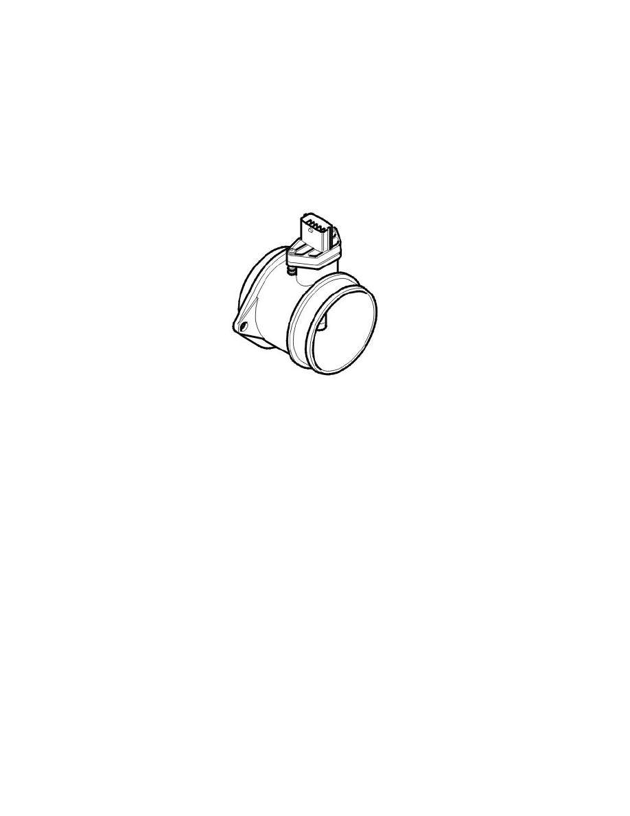
Mass air flow sensor
The mass air flow (MAF) sensor gauges the air mass sucked into the engine. It continuously transmits signals to the engine control module (ECM) about
the mass of the intake air. This data is used by the engine control module (ECM) to calculate:
-
the injection period
-
the fuel pressure
-
the ignition timing
-
turbocharger (TC) boost pressure (turbocharged engines only)
-
the engine load.
The transmission control module (TCM) also uses this data for its gear shift calculations. This data is transmitted to the transmission control module
(TCM) from the engine control module (ECM) via the high speed side of the Controller area network (CAN).
The mass air flow (MAF) sensor consists of a plastic housing with connectors, test electronics and an aluminum heat sink. The test electronics in the
mass air flow (MAF) sensor consist of a hot film comprised of four resistors. The hot film is cooled by the air flow to the engine.
The mass air flow (MAF) sensor is supplied with battery voltage by the system relay and is grounded in the engine control module (ECM). The signal
from the sensor is analog and varies between approximately 1-5 V depending on the air mass. Low air flow (low mass) results in low voltage, high air
flow (high mass) gives high voltage. No air flow gives a reading of approximately 1 V.
The mass air flow (MAF) sensor is positioned between the air cleaner (ACL) housing and the intake manifold.
The shape of the mass air flow (MAF) sensor is slightly different on naturally aspirated engines and also contains an air temperature sensor.
The engine control module (ECM) can diagnose the mass air flow (MAF) sensor. The signal can be read using VIDA.
Boost pressure sensor