
C70 L5-2.4L Turbo VIN 63 B5244T7 (2003)
C Connector
C. Component number
The second part of the component description concerns the specific component itself, e.g. light switch, central locking motor, etc.
Table
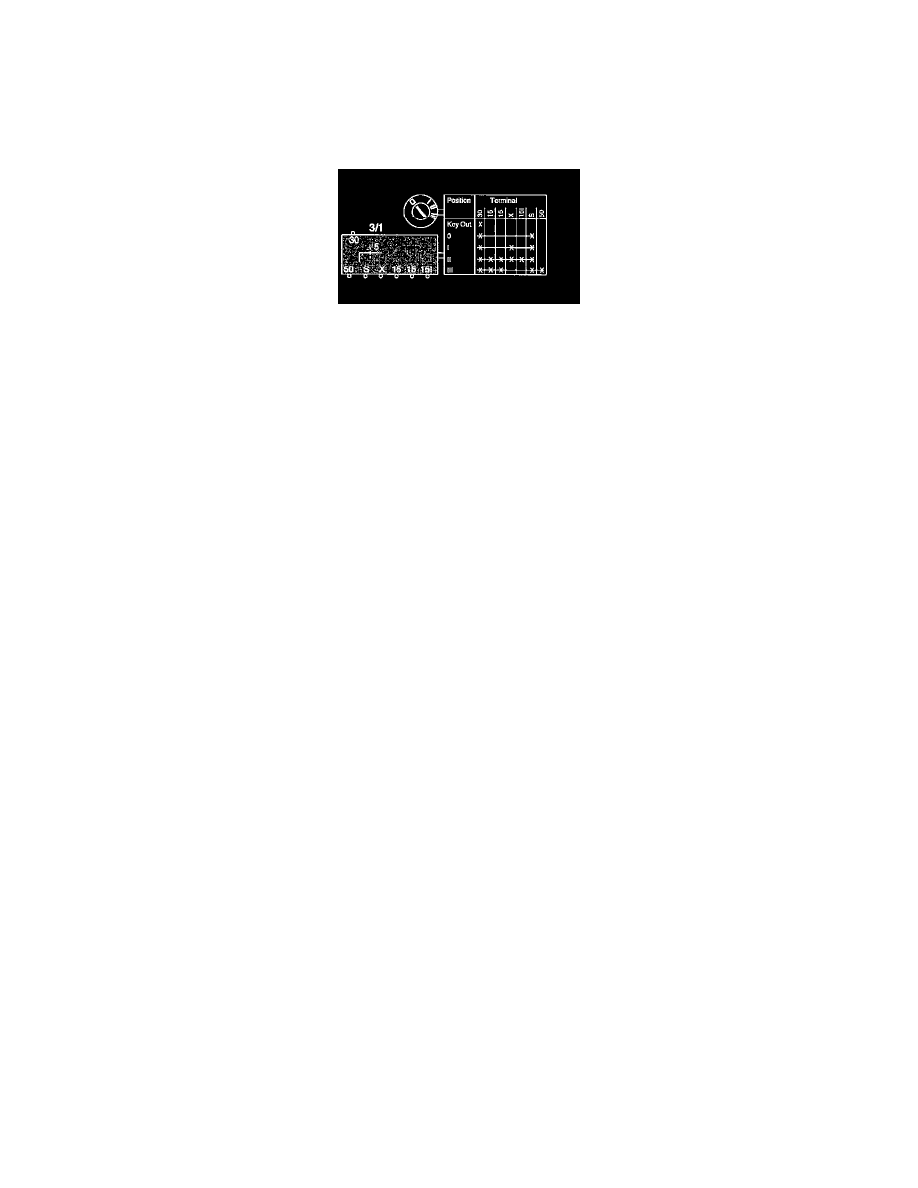
Certain multi-way switches are described in this information according to a table; see example below. The table indicates when the various connections
are electrically connected to one another.
E.g. in position III connection 30 is connected with connections 15A, S and 50.
D. Junction points
Junction points are numbered. This information contains a list of the various junction points, showing which other components the points are joined to.
See: Power and Ground Distribution/Branching Point/Diagrams/Electrical Diagrams
The location of the junction points is shown in the "Cable harness routing in vehicle". See: Locations/Harness Locations
E. Electrical distribution
The supply to the fuse is shown in "Electrical distribution". See: Power and Ground Distribution/Diagrams/Electrical Diagrams
F. Abbreviations
A number of different abbreviations are used which are explained "Wire Color Code and Other Abbreviations". E.g. R-W = red-white. See:
Diagrams/Diagram Information and Instructions/Wire Color Code Identification and Other Abbreviations
G. CAN communication
Disconnected wires are shown in their entirety in "Data communication". See: Powertrain Management/Computers and Control Systems/Information
Bus/Diagrams/Electrical Diagrams
H. Components
This shows which positions the various wires can be connected to for each component.
J. Location of components
This shows where in the vehicle the components are located.
K. Connectors
Connectors linking the cable harnesses to each other are described in "Connector Views". See: Diagrams/Connector Views
List of Components By Component Number
1/1
Battery
2/1
Headlight Relay With Bulb Failure Sensor
2/2
Fog-light Relay
2/4
Windshield-wiper Relay
2/5
Seat-belt Reminder/key-warning Relay
2/6
15l Supply Overload Relay
2/11
Electric Cooling-fan Relay
2/14
Glow Plug Control Relay