
C70 L5-2.4L Turbo VIN 63 B5244T7 (2003)
Core wings
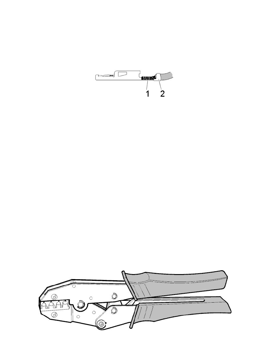
The core wings (1) are designed to make the electrical connection with the stripped section of the cable (the copper core).
Insulation wings
The insulation wings (2), relieve the core crimp wings from mechanical stress and are located on the insulating sheath around a cable.
The illustration shows a crimped cable terminal without seal.
Core crimp - electrical efficiency
The electrical characteristics for conduction for a contact are that it should be as least as efficient as the cable to which it is connected and provide good
contact.
These characteristics are dependent partly on the crimping process to fix the terminal on the cable and partly on the contact made between the two
terminals (male and female) in the connector.
The goal is to get a joint with the lowest possible transient resistance and to retain a low resistance even after extended periods of exposure (temperature
extremes, mechanical wear etc.)
Core crimp - mechanical efficiency
The joint in the core wings must retain the cable and support it so that it is not subjected to excessive bending forces at the entry point.
Choice of Crimp Tool
Choice of crimp tool