
C70 L5-2.4L Turbo VIN 63 B5244T7 (2003)
-
Replace the connector cover by depressing the locking catches (one on each side).
Check that the catches have engaged properly.
-
Push rubber seal into place.
Example 4
Example 4
Socket type housings p/n 1362989-4, and corresponding pin housings
Replacement of cable terminals
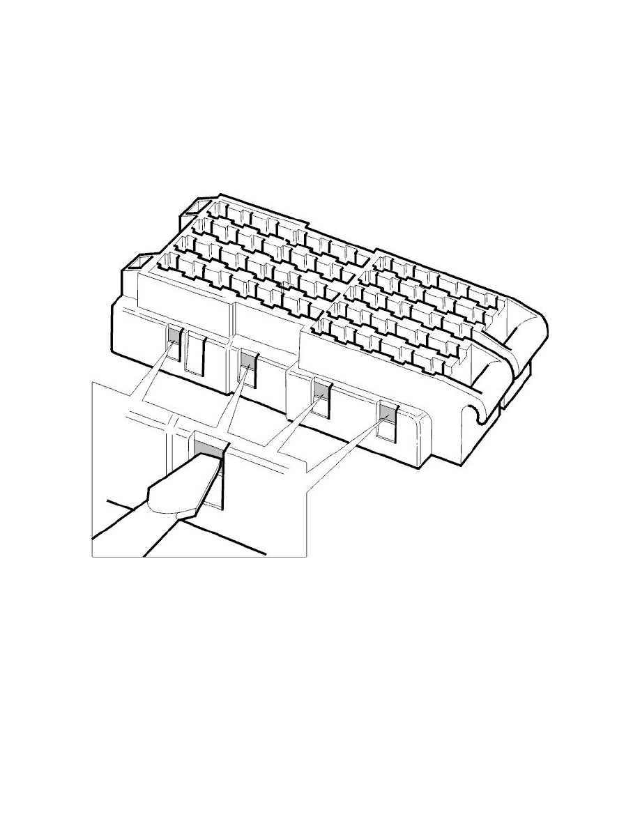
Open the housing
Hold the housing as shown and open the secondary locking as follows:
-
Using a small screwdriver press the catches on the secondary locking in from the side shown in the illustration. A "click" will be heard.
When the secondary locking is pressed in the locking cover slides open and the cavities open.
Extract the cable terminal
Follow instructions in Cavity opening with one extraction groove See: Extracting the Cable Terminal From the Housing/Cavity Opening With One
Extraction Groove.
Crimp new cable terminal