
S40 T5 L5-2.5L Turbo VIN 68 B5254T3 (2006)
Connection Of Breakout Box, Integrated Audio Module (IAM)
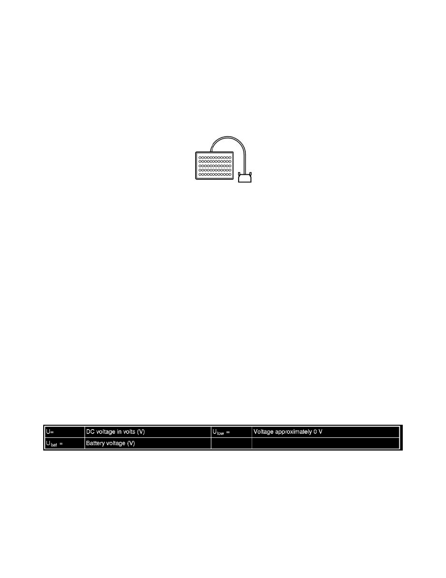
Connecting the breakout box
Special tools:
951 2977 IAM adapter See: Tools and Equipment/951 2977 IAM Adapter
951 1428 Breakout box See: Tools and Equipment/951 1428 Breakout box
951 1499 Cable See: Tools and Equipment/951 1499 Cable
981 3190 Replaced by 9511428 See: Tools and Equipment/981 3190 Replaced by 9511428
Connecting the breakout box
-
Ignition off
-
Remove the fuse.
-
Remove the infotainment control module (ICM).
-
Unplug the control module connector.
Plug adapter951 2977 IAM adapter See: Tools and Equipment/951 2977 IAM Adapter into the control module connector and connect breakout box951
1428 Breakout box See: Tools and Equipment/951 1428 Breakout box and cable harness951 1499 Cable See: Tools and Equipment/951 1499 Cable
to the adapter.
Alternatively, breakout box981 3190 Replaced by 9511428 See: Tools and Equipment/981 3190 Replaced by 9511428 could be connected to the
adapter.
Disconnect the breakout box in reverse order.
Other information
-
Signal description, Integrated Audio Module (IAM) See: Pinout Values and Diagnostic Parameters/Signal Description, Integrated Audio Module
(IAM)
-
For information on fuses, see the relevant wiring diagram.
-
General audio player module See: Entertainment System Control Module/Service and Repair
Signal Description, Audio Module (AUD)
Signal specification
General
All the values given below are between the respective terminal in column 1 and terminal #A2 in column 2 (power ground) unless otherwise stated in
brackets after the table entry.
Note! It is important to connect the breakout box and check the ground terminals before taking readings.