
S60 L5-2.4L VIN 64 B5244S6 (2003)
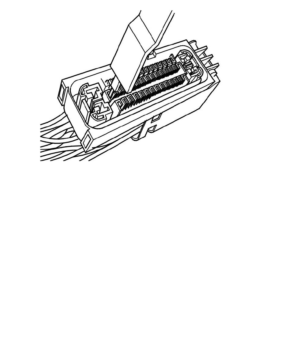
Use tools 951 2636 Terminal removal tool See: Tools and Equipment/951 2636 Terminal Removal Tool or951 2639 Terminal removal tool See: Tools
and Equipment/951 2639 Terminal Removal Tool to remove the primary lock, as illustrated.
At the same time pull the cable carefully backwards.
Connector, assembling
Note! Wheel sensor cables are twisted pair (positive and negative signal) cables for each wheel. It is important that paired cables are twinned in
the same way when they are reinstalled in the connector. The cables must be twisted approximately 3 times per 100 mm.
Primary lock
Check that the cable terminal is undamaged.
Press the cable terminal into the housing.
Check that the cable terminal is properly locked by pulling carefully on the cable.
Secondary lock
Press the secondary lock into place.
Connector Control Module for Anti-lock Brake System Module (ABS), Repair
Connector control module for Anti-lock Brake System Module (ABS), repair
Special tools:
951 2630 Terminal removal tool See: Tools and Equipment/951 2630 Terminal Removal Tool
951 2631 Terminal removal tool See: Tools and Equipment/951 2631 Terminal Removal Tool.
Note! As the illustrations in this service information are used for different model years and / or models, some variation may occur. However,
the essential information in the illustrations is always correct.
Connector, dismantling
Secondary lock